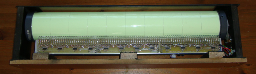
From the moment I've made my Morse code toy I knew that this glow in the dark material was meant to be used for bigger things. So... I've decided to make something bigger... a display based on the same principle. This time not with one white LED, but with many many more Ultra Violet LEDs. This because UV is simply much more efficient in transferring the energy into the glow in the dark material. And considering I need 94 of these LEDs, which can be all active at the same time, efficiency is a bit of an issue.
 You can watch a small video I made. Where the functionality of this device (all the way at the end of the video) is shown briefly. It is intended to be used as a YouTube subscriber counter and clock. But technically it can display all sort of information, since it basically is a 2x16 character dot-matrix display.
 When the project began, I started with great enthusiasm, made the LED driver PCB's, programmed a microcontroller, doing the mechanics, and wrapped 10 pieces of glow in the dark tape around a 55cm long PVC pipe. It all went pretty smooth and quickly proved to be working pretty well as a display (works best in the dark). But there was one detail. All clocks requires to display the correct time. And I wanted this clock to be a perfect clock (low drift, easy to configure, etc). So that could be an issue. Because I could not make up my mind how to solve that problem (as simple as possible), the project was put aside... and we all know how that could end... in a permanently unfinished project.
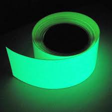
Though the clock was never out of my mind as I kept it underneath my bed (for quick access in order to finish it). But because at daytime the display charged with ambient light it noticeably glowed during the night. And because I used the heavy duty glow in the dark tape. The tape I used was designed/intended for use along stairways, or to mark exits. To indicate hazardous areas or safe passages in situations when the light suddenly fades. Imagine an exit in a bar somewhere, suddenly the lights go out, where is the exit, I can't see, it's dark. Then there is the opening of the door clearly marked by a mysterious green glow of the tape. Clearly visible and you can safely reach the exit. Wonderful stuff. So being heavy duty tape, meant to be glowing for hours after being charged, I meant that it could be charged up so bright that you could read a book with it (well only for a few minutes directly after charging), you must be aware that brightness quickly fades to a much much lower level. But more then bright enough to remain very clearly visible at night.
So therefore you see the mysterious glowing pretty well at bedtime. With a roll of this underneath my bed (close along the edges) you can imagine that, if you don't realize what's causing that mysterious green glow, the mysterious light could be enough to keep you awake. A problem that was easily solved by a putting a towel over it. And so the half finished project remained under my bed, wrapped in a towel for a very long time. Before I knew it, the years went by.
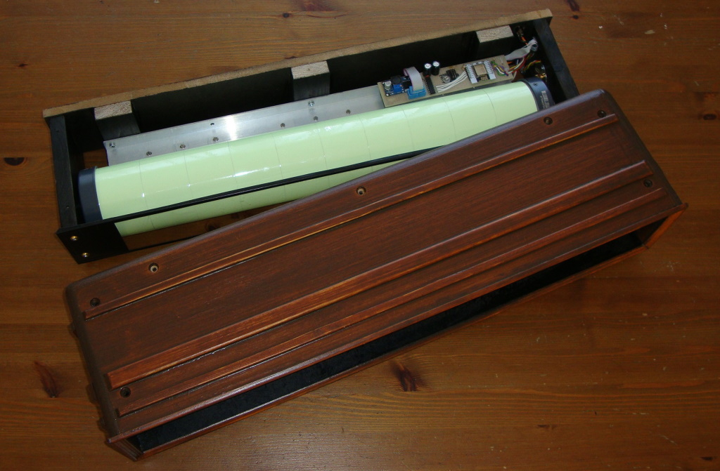
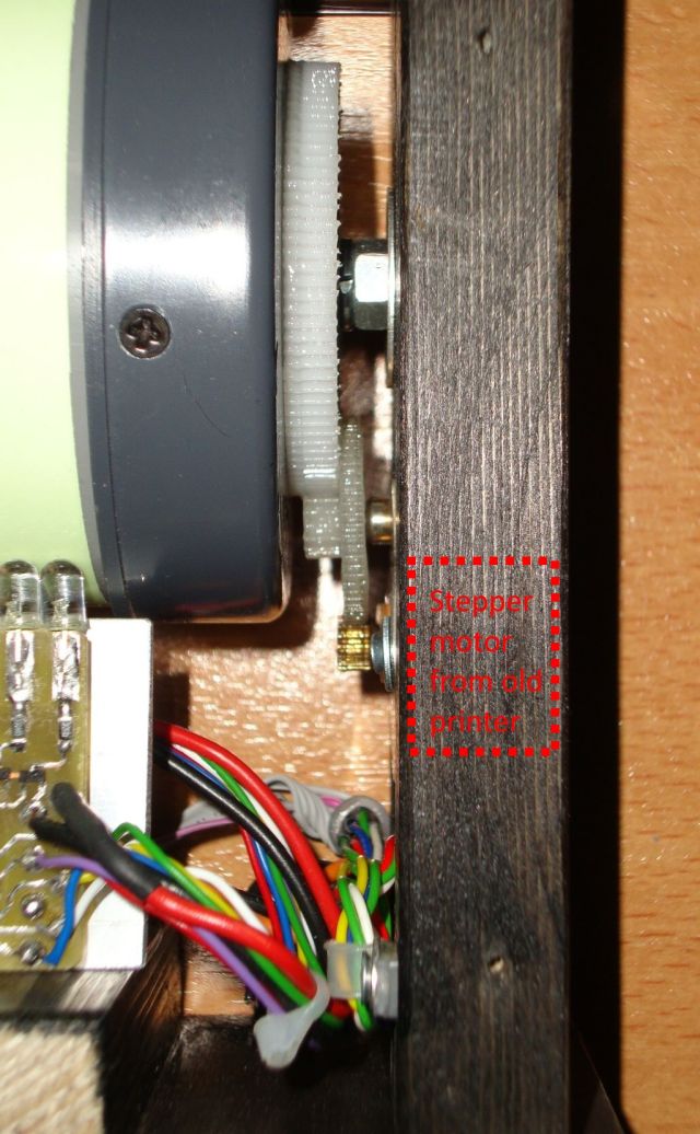 The roll itself is just a simple PVC pipe with endcaps. Attached to one of those endcaps is a sprocket or gear or cog-wheel (or whatever it is called these days). On both of the endcaps there are some standard ball bearings to make it all spin very easily. Just some cheap inline-skates-wheel ball bearing. Nothing fancy. The stepper with gears originates from an old printer. An old matrix printer if I'm not mistaking. I salvaged those parts many many years ago. So it was nice that I could finally use them in a project. Which also proved my right in saving it for all these years. Now, the stepper motor is very small, which has an advantage because this way I could fit in into the side of the cabinet. The motor is indicated with red rectangle in the photo below. It is all very very basic. As an axle I used a piece of threaded rod slightly longer then the length of the PVC pipe. The pipe lays on this threaded rod with the bearings. I used a thread rod for simplicity and to make sure that both bearing were rotating along the same line. Making it less wobbly then two small axels (one on each side). There is only one tiny problem, the stepper motor has almost no power, the gears make it better, but still. Lowering the speed increases torque, which is normal for a stepper but too slow would make it look bad. Fortunately I could drive it fast enough to be acceptable.
 It was march 2018 that I suddenly realized that I should all base it on an ESP8266. The last few years I've gained a lot of experience with this wonderful piece of technology (a cheap module but priceless in its possibilities and performance). So I removed the old microcontroller and put in the new ESP8266 (an ESP-12E to be exact). I ported the code I had to the ESP, modified some existing code from the internet to monitor the YouTube stats, re-used some of my NTP code from another ESP project. Funny though, for years I've been pondering how to finish it. And then suddenly BAM... inspiration... and with renewed energy it was working like I wanted it to be in a weekend. Now the only thing I needed to do was to make a nice enclosure for it, that took me another weekend. And in the days in between I decided how it should look. I decided that it had to look a little like wood, to match the cabinet. But also to make it look a little like an old radio, or at least not something like I made myself (because it has to be nice to look at). Though considering my woodworking skills and budget I decided to use some simple MDF and some small strips of wood bought from the hardware store.
Though first I have to make my improvised mechanics a little sturdier. So I threw away the old base, which was nothing more then a crooked plank and used a straight piece of MDG. Which I painted mostly black on the placed were it could matter. The piece of plexiglass you see in the photo below, was one of the last things added to the design. As you can see the whole unit will slide in and out of the case easily. Fixing it with (perhaps a little too many) screws on the top... and bottom. So if I ever need to do some repair to the mechanics, LED's or ESP I can easily reach all locations of the device.
 So I ended up making a simple rectangular box, screwed and glued it all together. Rounded the corners and edges using a plane and some sandpaper and glued on the wood strips. At first I wanted to stain the whole case with very dark colored furniture wax. But that wasn't as nearly as dark and colorful as I imagined. Fortunately I tried it on a piece of scrap MDF first, so no harm was done. Then I decided to use some stain and a large brush and even for the little effort I've needed to put in the staining process, it performed miracles. To get a little bit of darker coat, I stained it again a few days later. I was very pleased with the result. As the photo shows, the 2 pieces fit together perfectly. Aka... not perfect... more like a tight glove.
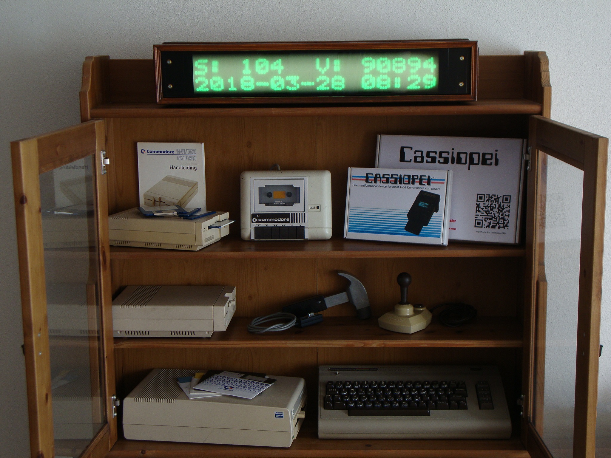
 The end result is shown below. Here you see the glow in the dark display acting like a YouTube counter on the top line (=subscribers, V=views) to my YouTube channel. And on the bottom line there is the date and the time. The display is updated every 30 seconds. Which is more then enough in the evenings. Regarding the daytime, this kind of display is useless. Because the strength of daylight is so much that it completely overwhelms the light output of the glow in the dark characters. Meaning that the characters would only be visible for a few seconds after being written. But is this a problem, no not really. Mostly because the clock is not really in active use... As there are 2 small issues, first: the clock makes a slight humming noise each time it updates. Not loudly, but noticeable when the house is completely silent (no TV or radio), this is a problem for me personally and most likely a problem for the WAF. Second: the cabinet on which the clock was to be placed isn't that empty any more as it was when I started the project 3 years ago. In other words the situation in real life isn't completely as shown in the picture below. When I started this project in 2015 the top and most of the shelves were completely empty, but over the years all sort of photos, "art" and "school projects" were placed on all the shelves. So eventually in 2018, there was no longer any room left for the clock. But we agreed that I could make a demonstration picture of my project, so I could properly show it here on my website and after that restore the contents of the cabinet back to normal. This way I could show the whole clock as it was intended and I could mentally file this project under the tab "finished".
 The ESP8266 is a great device, cheap but powerful and a lot of examples can be found if you program it using the Arduino programming environment. So... that's what I used and it served me very well. The code for the YouTube stats is basically the code from Brian Lough slightly modified to my own taste. This code is very much used by YouTube counters as featured on YouTube in combination with the ESP8266. The code for the NTP server is worked on by many people, Michael Margolis, Tom Igoe, Ivan Grokhotkov and then modified to suit my own needs as I wanted NTP functionality, but didn't want a clock that spammed the NTP server. So I request the time... then sync my own internal clock to that time and periodically re-sync the clock to maintain accuracy. In order for the code to run, you do need to supply your own API-key for YouTube AND the YouTube channel-ID. Also you need to fill in your own WIFI network SSID and KEY.
In essence, the fosforesence effect is used to store the information and therefore it doesn't really matter if you use an electrontube or an LED to send energy into the material used for storage. Anyway, since storage is cheap these days it makes no sense to make such a memory based on glow-in-the-dark tape, some LEDs and some photoreceptors (with the proper circuit an LED could also be used to detect light). However, this kind of project would be completely useless today, but it could demonstrate the method of storage in a volatile media. How fun would it be to see this rotating roll storing data. Though there is one slight problem, the decay time is very long, so erasing data from this roll would be difficult or just take a long time. Although there are some videos going around that with the proper wavelength of IR-light you could darken areas of the glow-in-the-dark materials. But quick tests indicates that the tape I used was not reacting to IR-light at all. Therefore I expect this tape to have some sort of IR blocking coating but it could very much also be the case that I just used the wrong IR-leds or that I did not send enough IR light. Enough material to think about...
You can watch a small video I made. Where the functionality of this device (all the way at the end of the video) is shown briefly. It is intended to be used as a YouTube subscriber counter and clock. But technically it can display all sort of information, since it basically is a 2x16 character dot-matrix display.
How it all started
It all started in 2015... we've just bought a new cabinet. At that time the top shelf was completely free and had more then enough room for a large display or clock. The perfect place for my new glow-in-the-dark-tape-on-a-roll display. But if a made such a display, how large should it be, what should it be displaying. Ehmmm... considering that this is very similar to a classic dot-matrix LCD, I think it should be able to fit at least two lines. The most efficient way of charging the tape is by using UV-light. And UV LED's are cheap on ebay, so I bought a bag of 100. Knowing that I had this many LEDs available I calculated the a 16 char display was possible. The display area would be approx 50 cm wide and using the piece of PVC pipe I had still laying around, it would be capable of fitting 2 lines. So I would be building a 2x16 char display, using LED's and glow in the dark tape. With 16 chars it would mean that I would require 96 LEDs, leaving me 4 spare LEDs... just in case. Well I can tell you know that that wasn't enough. Because of a silly mistake I fried some of the LEDs during a brightness experiment. So I needed to order another 100. But ordering things from ebay is tricky and so I ended up with LED's that were slightly different in light output and angle, but in the end I could compensate for that. So I you are intending to build this kind of thing and order from ebay... by double the components you need, just in case you need spares.Starting the build
As I wanted to keep my options open I decided on LEDs in between the chars so that I could always decide to make it a graphic display with a variable font or whatever. So 96LEDs and a display of 50cm wide... plus some extra cm for endcaps, motor, bearings, etc. would soon lead to a total size of more then 65cm. Being 10cm tall, it is a pretty large display for only 2x16 characters. I decided to turn it into a clock combined with a YouTube counter, just for fun. And hey... everybody needs a good clock,. might as well make it a non conventional one.
When the project began, I started with great enthusiasm, made the LED driver PCB's, programmed a microcontroller, doing the mechanics, and wrapped 10 pieces of glow in the dark tape around a 55cm long PVC pipe. It all went pretty smooth and quickly proved to be working pretty well as a display (works best in the dark). But there was one detail. All clocks requires to display the correct time. And I wanted this clock to be a perfect clock (low drift, easy to configure, etc). So that could be an issue. Because I could not make up my mind how to solve that problem (as simple as possible), the project was put aside... and we all know how that could end... in a permanently unfinished project.
Though the clock was never out of my mind as I kept it underneath my bed (for quick access in order to finish it). But because at daytime the display charged with ambient light it noticeably glowed during the night. And because I used the heavy duty glow in the dark tape. The tape I used was designed/intended for use along stairways, or to mark exits. To indicate hazardous areas or safe passages in situations when the light suddenly fades. Imagine an exit in a bar somewhere, suddenly the lights go out, where is the exit, I can't see, it's dark. Then there is the opening of the door clearly marked by a mysterious green glow of the tape. Clearly visible and you can safely reach the exit. Wonderful stuff. So being heavy duty tape, meant to be glowing for hours after being charged, I meant that it could be charged up so bright that you could read a book with it (well only for a few minutes directly after charging), you must be aware that brightness quickly fades to a much much lower level. But more then bright enough to remain very clearly visible at night.
So therefore you see the mysterious glowing pretty well at bedtime. With a roll of this underneath my bed (close along the edges) you can imagine that, if you don't realize what's causing that mysterious green glow, the mysterious light could be enough to keep you awake. A problem that was easily solved by a putting a towel over it. And so the half finished project remained under my bed, wrapped in a towel for a very long time. Before I knew it, the years went by.
The roll itself is just a simple PVC pipe with endcaps. Attached to one of those endcaps is a sprocket or gear or cog-wheel (or whatever it is called these days). On both of the endcaps there are some standard ball bearings to make it all spin very easily. Just some cheap inline-skates-wheel ball bearing. Nothing fancy. The stepper with gears originates from an old printer. An old matrix printer if I'm not mistaking. I salvaged those parts many many years ago. So it was nice that I could finally use them in a project. Which also proved my right in saving it for all these years. Now, the stepper motor is very small, which has an advantage because this way I could fit in into the side of the cabinet. The motor is indicated with red rectangle in the photo below. It is all very very basic. As an axle I used a piece of threaded rod slightly longer then the length of the PVC pipe. The pipe lays on this threaded rod with the bearings. I used a thread rod for simplicity and to make sure that both bearing were rotating along the same line. Making it less wobbly then two small axels (one on each side). There is only one tiny problem, the stepper motor has almost no power, the gears make it better, but still. Lowering the speed increases torque, which is normal for a stepper but too slow would make it look bad. Fortunately I could drive it fast enough to be acceptable.
Continuing the build
It was march 2018 that I suddenly realized that I should all base it on an ESP8266. The last few years I've gained a lot of experience with this wonderful piece of technology (a cheap module but priceless in its possibilities and performance). So I removed the old microcontroller and put in the new ESP8266 (an ESP-12E to be exact). I ported the code I had to the ESP, modified some existing code from the internet to monitor the YouTube stats, re-used some of my NTP code from another ESP project. Funny though, for years I've been pondering how to finish it. And then suddenly BAM... inspiration... and with renewed energy it was working like I wanted it to be in a weekend. Now the only thing I needed to do was to make a nice enclosure for it, that took me another weekend. And in the days in between I decided how it should look. I decided that it had to look a little like wood, to match the cabinet. But also to make it look a little like an old radio, or at least not something like I made myself (because it has to be nice to look at). Though considering my woodworking skills and budget I decided to use some simple MDF and some small strips of wood bought from the hardware store.
Though first I have to make my improvised mechanics a little sturdier. So I threw away the old base, which was nothing more then a crooked plank and used a straight piece of MDG. Which I painted mostly black on the placed were it could matter. The piece of plexiglass you see in the photo below, was one of the last things added to the design. As you can see the whole unit will slide in and out of the case easily. Fixing it with (perhaps a little too many) screws on the top... and bottom. So if I ever need to do some repair to the mechanics, LED's or ESP I can easily reach all locations of the device.
Almost finished
So I ended up making a simple rectangular box, screwed and glued it all together. Rounded the corners and edges using a plane and some sandpaper and glued on the wood strips. At first I wanted to stain the whole case with very dark colored furniture wax. But that wasn't as nearly as dark and colorful as I imagined. Fortunately I tried it on a piece of scrap MDF first, so no harm was done. Then I decided to use some stain and a large brush and even for the little effort I've needed to put in the staining process, it performed miracles. To get a little bit of darker coat, I stained it again a few days later. I was very pleased with the result. As the photo shows, the 2 pieces fit together perfectly. Aka... not perfect... more like a tight glove.
The end result is shown below. Here you see the glow in the dark display acting like a YouTube counter on the top line (=subscribers, V=views) to my YouTube channel. And on the bottom line there is the date and the time. The display is updated every 30 seconds. Which is more then enough in the evenings. Regarding the daytime, this kind of display is useless. Because the strength of daylight is so much that it completely overwhelms the light output of the glow in the dark characters. Meaning that the characters would only be visible for a few seconds after being written. But is this a problem, no not really. Mostly because the clock is not really in active use... As there are 2 small issues, first: the clock makes a slight humming noise each time it updates. Not loudly, but noticeable when the house is completely silent (no TV or radio), this is a problem for me personally and most likely a problem for the WAF. Second: the cabinet on which the clock was to be placed isn't that empty any more as it was when I started the project 3 years ago. In other words the situation in real life isn't completely as shown in the picture below. When I started this project in 2015 the top and most of the shelves were completely empty, but over the years all sort of photos, "art" and "school projects" were placed on all the shelves. So eventually in 2018, there was no longer any room left for the clock. But we agreed that I could make a demonstration picture of my project, so I could properly show it here on my website and after that restore the contents of the cabinet back to normal. This way I could show the whole clock as it was intended and I could mentally file this project under the tab "finished".
The ESP8266 is a great device, cheap but powerful and a lot of examples can be found if you program it using the Arduino programming environment. So... that's what I used and it served me very well. The code for the YouTube stats is basically the code from Brian Lough slightly modified to my own taste. This code is very much used by YouTube counters as featured on YouTube in combination with the ESP8266. The code for the NTP server is worked on by many people, Michael Margolis, Tom Igoe, Ivan Grokhotkov and then modified to suit my own needs as I wanted NTP functionality, but didn't want a clock that spammed the NTP server. So I request the time... then sync my own internal clock to that time and periodically re-sync the clock to maintain accuracy. In order for the code to run, you do need to supply your own API-key for YouTube AND the YouTube channel-ID. Also you need to fill in your own WIFI network SSID and KEY.
Thoughts...
Now this display is all for fun... though the materials used are potentially memory elements. I used it to store light, but I could also use it to store information. In the "good old days" they did this using CRTs. Memories based on CRTs were called Williams tubes. Very interesting technology!In essence, the fosforesence effect is used to store the information and therefore it doesn't really matter if you use an electrontube or an LED to send energy into the material used for storage. Anyway, since storage is cheap these days it makes no sense to make such a memory based on glow-in-the-dark tape, some LEDs and some photoreceptors (with the proper circuit an LED could also be used to detect light). However, this kind of project would be completely useless today, but it could demonstrate the method of storage in a volatile media. How fun would it be to see this rotating roll storing data. Though there is one slight problem, the decay time is very long, so erasing data from this roll would be difficult or just take a long time. Although there are some videos going around that with the proper wavelength of IR-light you could darken areas of the glow-in-the-dark materials. But quick tests indicates that the tape I used was not reacting to IR-light at all. Therefore I expect this tape to have some sort of IR blocking coating but it could very much also be the case that I just used the wrong IR-leds or that I did not send enough IR light. Enough material to think about...