I also made a video to demonstrate the device, see link below:
What is it:
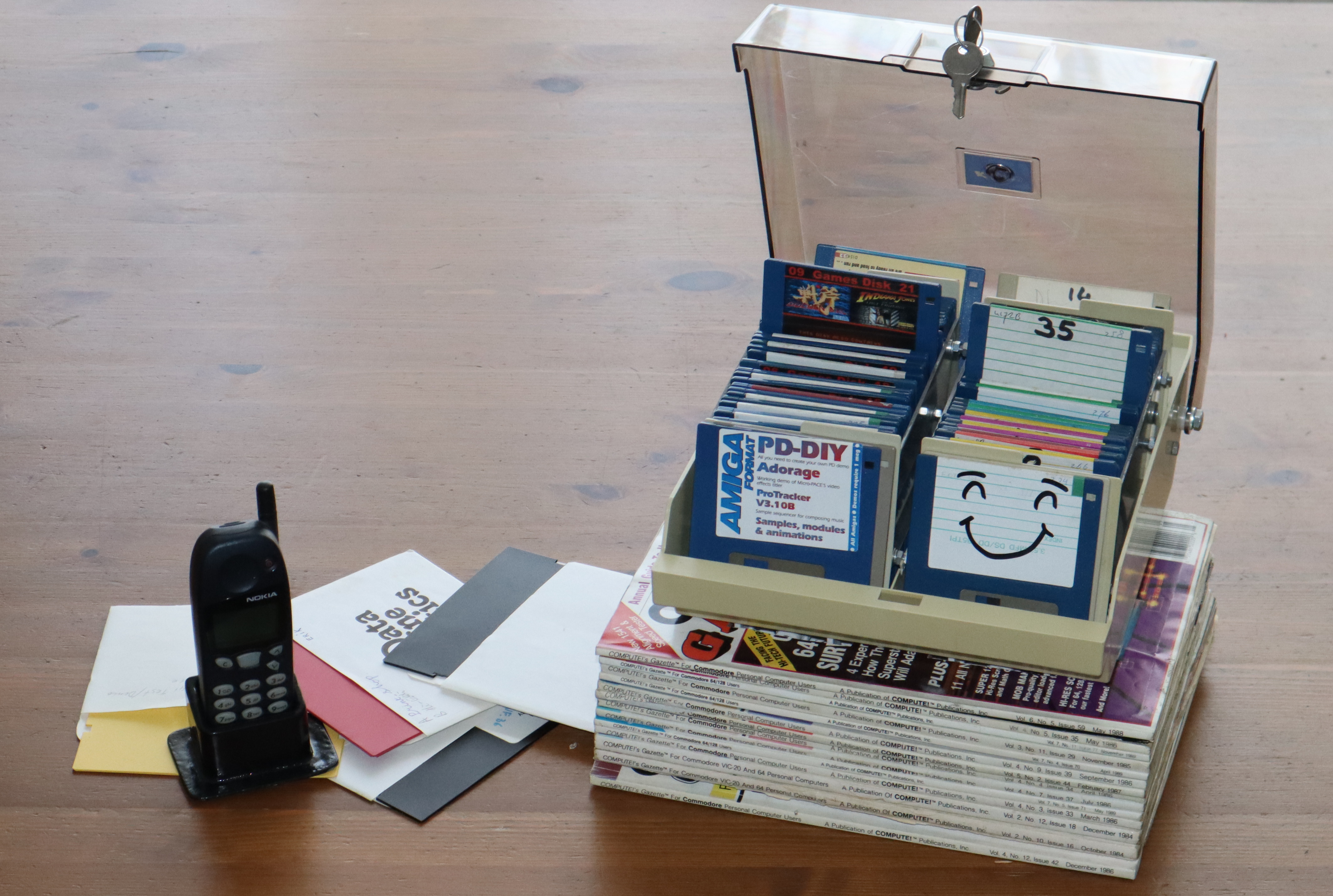
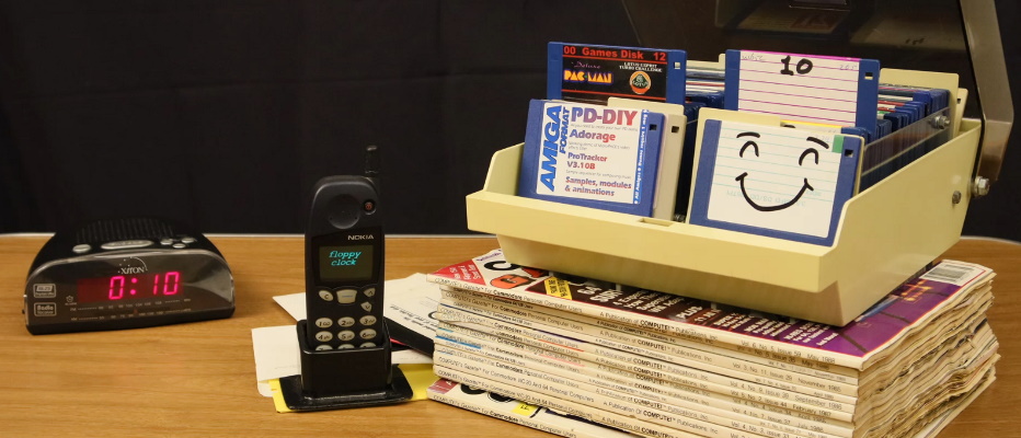
Some might say it is a piece of art, but technically it's a clock made using a storage box for 3.5 inch floppy disks.
The intention of this project is to have an ordinary diskbox, with two disks slightly lifted so you could read the label of the disk in order to determine the time of day. It's a 12 hour clock, with a resolution of 5 minutes, the idea is to be very, very subtle, it's therefore more of a secret clock. If you are not aware of it, it just looks like an innocent box of disks. I thought it to be funny if people would gradually notice that the box of disks is not ordinary at all. And that they eventually notice that the labels on the disk have approximately the same numbers as the current time. It's when they have that "aha... now I get it" moment when the project shines. Hopefully resulting in a smile and some amazement by the observer.
However, that's the basic concept in my mind. But reality is different... What I expect to happen, is that nobody will notice it at all. Or that my family (who has to live with this contraption in their house) will individually wonder what is making that humming noise every 5 minutes and kindly ask if it can be stopped. So therefore I have to conclude that the thing I'm making is more of a piece of moving art. Which is only to be powered up on special occasions.
So why am I'm doing this? That is a sensible question to the casual observer, but the only reason is "because I think I can", the whole project is a giant puzzle (a simple idea with terrible pitfalls) from start to finish. A puzzle that is more about the journey than the destination. And when it's finished I have something that will be worthless in so many ways. But I have filled my backpack filled with experience that will most certainly come to my aid in one of my future projects, which can be at home or in a more professional environment. But I do this project mostly because I think it will be fun.
How the idea came up:
Considering my hobby of retro computing, I'm familiar with floppy disks. Although I don't use all that much, they are fun (nostalgia) or sometimes required to be used from time to time. In a period where I made some small videos about doing silly things with floppy disks. I figured that perhaps it would be fun to use these disks to tell time. But how would I do that, a flip-flap mechanism... nehh that would be fun, but too large.
How about a box of disks where one disk rises to indicate the minutes and another box next to it, where a disk rises to indicate the hours. Every disk has a label, so 12 disks are required to indicate each hour. 60 disks for the minutes would be a little to big. Nehh... I guess that 12 disks for the minutes would be fine (steps of 5 minutes), this also makes the clock less noisy as it only needs to move once every 5 minutes.
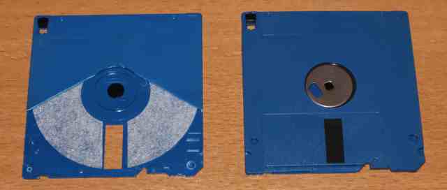
Then I realized that 5 1/4 inch disk are really light thin and floppy (hence the name), perhaps 3.5 inch disks are better. The thickness makes them a bit easier to handle, their weight makes them more reliable to fall down (although not as reliable as I hoped for as I would found out in the end). Although the thicker disk will make the clock larger in depth, it does allow for easier hiding of the mechanisms to be involved. So I decided to step away from using the 5 1/4 inch disk and instead use the just as iconic 3.5 inch disk. The latter is perhaps even a better choice as more (modern) people will know this type of disk, simply because it is still used as the save icon in many programs.
How I wanted to make it... but didn't:
As with most of my projects, this project encountered many problems. It all began with how to make a single disk emerge from a row of disks. My first idea was to make a construction that uses two motors (per row of disks). One motor for moving the lifting mechanism from back to front and the another motor to make the lifting mechanism move the disk up and down. This all had to be compact, and it had to be as simple as possible. Because simple things have a certain beauty, one of those is the challenge of making it simple (which can be very hard sometimes). Simple things have the benefit of easy assembly, maintenance and repair. But mostly because simple things can be less expensive.
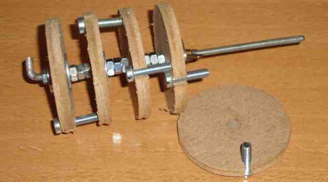
So to keep it simple, I thought of making this mechanism out of a 2 pieces of 10x10mm angled aluminum and a piece of M4 threaded rod and nut (and some 3D printing to keep it all together plus a ball bearing to keep it smooth and reduce wear where needed). It isn't very efficient regarding speed and motion, but it would do the job. The whole construction could be made relatively compact with a motor on each side of the mechanism. So all motors will be directly coupled and no belts or sprockets are required. This also needs a fool-proof method of making sure that all the discs stay in their own place (but can move up and down freely without wiggling (which causes them to get stuck)), but that's just a collection of static parts, guides you may call them, and they are not shown here.
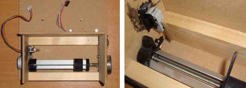 But when I started to experiment with this setup, I quickly realized that the movement need to be controlled very precisely (not a big deal for a motor controlled threaded rod) but also that the disks would need to return reliably over and over again. If for some reason the alignment of the lifting mechanism isn't correct (relative to the disks that is), then two disks (instead of one) will rise, or even worse, no disk at all. Sure everything can be timed precisely and this whole setup can work flawlessly if done properly. But very soon, my mind came up with all sorts of things that can AND WILL go wrong while building the first one. However, having a mechanism based on M4 threaded rod would make it extremely slow. A problem that gets worse when driven by a heavily geared stepper like the 28BYJ-48, which is very small and cheap and therefore usable for this project. Some may consider this not to be a problem, but with the experience with the homing times of the linear clock project still fresh in my mind, I considered this to be a major testing obstacle. Now I did consider using two different kind of stepper motors, which you can see in the photo above, but I dropped this concept when I realized that it would result in a construction that was relatively big for what it needed to do (rotate a shaft). But also because 2 different kind of stepper motors just isn't a good looking solution. The best would be to drop the M4 threaded rod and go for a decent leadscrew, but that would be a part not present in my current parts bin. Either way, this construction requires two motors, two limit switches, two driver stages. Sure the design looks nice and simple, but not nice and simple enough. So I decided to reject this concept and put this entire project in a project box underneath the bed. So that I could literally sleep on it hoping that my subconscious mind eventually will come up with something better.
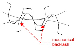 And fortunately many months later (almost a year, which technically is already two years since the beginning of the idea of making a floppy clock), I saw a video that inspired me. And it made me realize that the enemy an engineer most of the times tries to avoid, can sometimes can be a friend, that problem is called "backlash". The sollution to my project was "backlash" and lot's of it.
How I eventually made it...:
I was inspired by a video of a wooden 3-digit single dial combination lock made by Matthias Wandel. Now I didn't want to make a lock, I wasn't even interested in locks at all. I just stumbled upon this video and considering that Matthias has made many other interesting videos, I decided to watch this one. But when I noticed the principle of operation of these types of locks, I was amazed by it's simplicity. The interesting part about this lock design (which according to Wikipedia seems to be very common since the 1930's) is that the individual parts of each segments can be set into any desired position merely by driving a single shaft clockwise or counter clockwise. Although there are some restrictions, but these could actually make my clock design look more interesting to watch during operation (a wave-like motion of disks). So after watching that video I realized I had some pieces of scrap MDF already cut into circles, so I hastily assembled these to a setup with more then 3 cams. And tinkered with it for the rest of the evening. From then on I realized that this perhaps could be the most simple design possible for my application.
 When a gearbox has some "backlash" it means that there is some slack between the gears, a space between the tooth of the gears. This means that when the direction of the movement has to change this slack has to be overcome, preventing a perfect movement of the gears. In a 3D printer or CNC machine this would be visible in circles that are not perfectly round (tiny square edges on the sides). Backlash is therefore (in a machine that requires to be precise) an unwanted error that must be kept as small as possible. And their are various ways to achieve this.
But in case of the combination lock, backlash it is actually exploited to the max. Let's assume that the coupling between the two moving parts has a slack of 350 degrees. This will allow for one wheel to turn 350 degrees in the opposite direction (of the last position the gears touched perfectly) before both wheels start to turn. In other words, if you turn the first wheel clockwise until the second wheel catches on and starts moving, then if the first wheel is turned counterclockwise then the second wheel will do nothing for the entire distance of 350 degrees (which is almost a full turn of the first wheel). If you add a third wheel with the same amount of slack, then it will take 350+350=700 degrees (almost two full turns). If we add another wheel, that could be 1050 degrees (almost 3 turns). In other words, backlash allows us to decouple the wheels for almost an entire rotation of the main driving shaft. Now by carefully controlling the number of turns in combination with the appropriate turning direction, we can position every wheel in our system into almost every position. Meaning that in our situation (where we need only one disk to rise above the others) we can move each disk to the top or lower position and in any combination. There's only one catch, you cannot prevent the movements of all disk BEFORE the disk you want to move, but since movement can be undone by counter rotating this is not an issue. It is final position we care about. And honestly, the additional movement of the other disks can make it more pleasing to watch. And all of this with only one motor, one home switch and one driver. Technically the motor doesn't even have to be a stepper motor (if we would configure the home switch like the home-switch in a windshield wiper motor), but considering the cost and size of the 28BYJ-48 stepper motor and the easy way of driving them, there is no big advantage in using a DC motor.
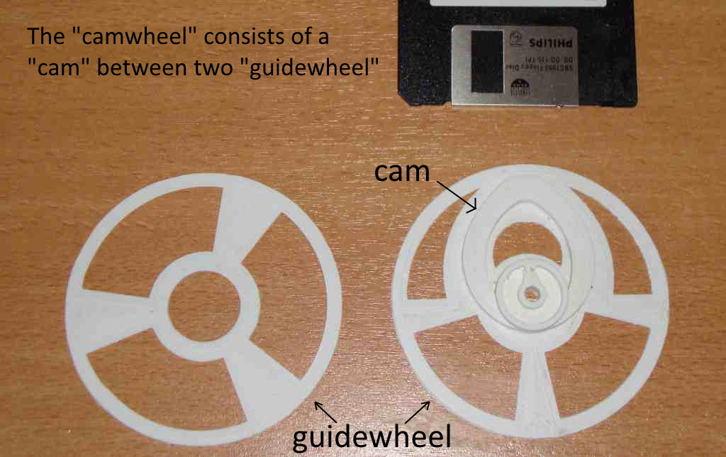
Now a problem with a setup like above is that everything will not stay in position by itself. I the situation of a lock, which only has 3 "wheels" that need to rotate, it's solved by having enough friction to hold the position of the individual "wheels". But in my case I will have many "wheels" that need to rotate and that the friction per "wheel" will quickly add up to a problematic value. Requiring a heavy motor to overcome this unwanted load. So How can we create a stable position without relying on friction? Well, it can actually be as simple as adding a straight edge to the cams that move the disk, this certainly will do the trick. So, by making the top of the cam having a flat surface, the disk itself will keep the cam in place once it reaches its highest position. Now you may wonder that this will also increase drag of some sort, which is true, BUT this drag exists ONLY on a very small part of the cam's movement. And considering that all the cams of the entire system are slightly out of phase, this drag will not really add up (or at least not as much as otherwise would be the case). For the flat surface on the cam, see the image below.
So with these ideas now set into my mind I started to draw something in FreeCAD and after 3 design iterations I ended up with a cam sandwiched in between to large rings. These rings are called guide-wheels, one wheel is printed together with the cam and is firmly attached, the other guide-wheel needs to be glued onto the cam (otherwise it will be very impractical to print). Below you'll see the construction before the two parts are assembled, keep in mind that one of these cam-wheels is required for each disk that needs to be lifted. Which would make a total of 24 (12 for the hours and 12 for the minutes). This is perhaps a lot of 3D printing, but it is a relatively easy print. At first I wanted to leave out the guide-wheels, but for reliability reasons I imagined that it's wise to have them. This way we are absolutely sure that the disk is always perfectly aligned directly above the cam. But we are also completely sure that the disk directly next to the disk that needs to be lifted is not moving due to friction with it's lifting neighbor. Although there will be friction of the disk against the cam-wheel and guide-wheel...
 If you look at the cam-wheel, you can see a notch in the center of the wheel. Inside this notch is to be placed a pin (which I initially made from a toothpick but eventually switched to using much stronger metal ones, cut from paperclips). These pins, I call driving pins, extend out of the cam-wheel for approx 5mm on the one side of the wheel (not shown here, see the video for more details). These pins are the only contact points between the cam-wheels. Each cam-wheel has a pin that locks onto the next cam-wheel. The pin travels freely inside a channel until it catches onto the notch of the next cam-wheel, which from that point on will also start to turn. Looking at the size of the notch and the thickness of the pin (2mm) we now know that the backlash in this system is approximately 32 degrees (which I reduced with a dremel to something smaller). Meaning that we have a freedom of movement of 328 degrees per wheel (a bit more after the dremel modification). Below is an image of how the disk would be placed inside this cam-wheel and how it will move up and down when the cam-wheel.
 Now you can debate on the perfect shape of the cam I drew, but as long as the disk(s) goes up and down, I'm happy. And yes, I'm aware of the fact that the lifting range can be slightly increased or optimized. This setup would require a dummy disk in between the moving disks. Which is completely intended, because this would make it look like more disks inside the diskbox are able to move (but technically, it is only halve). The guide-wheel keeps the moving disk always directly above the cam and it keeps the dummy disk isolated from the moving disk. This setup also allows for a small space between the cam-wheels. But also, if desired for whatever reason (which could be visual or practical), the final design could be spread out with some extra spacers.(br)
Calculations:
Now although the whole system is nothing more than a collection of 12 cam-wheels (originally I envisioned 13, one extra disk for displaying status info). Each connected to each other with approximately 350 degrees of slack all driven by a single motor. This simple construction does require some calculations and although not rocket science it does not need to be done correctly in order for the clock to properly function. First of all, we need to know exactly how many steps the motor needs to make to do a full rotation. Then we need to adjust that with the gearing ratio of the gearing system between the motor and the cam. And if we know exactly how much slack there is between each cam-wheel then we can calculate how many steps we need to do before the desired cam-wheel rotates the desired disk into the desired position. Though after that has happened, we must undo the movement of the cam-wheels that also had been driven in order to drive the cam-wheel that needed to be turned, so that in the end only the desired disk is in the desired position (up) and all other disks are down. Again all doable, but it needs to be done correctly. Oh, and don't forget to add the offset, since the home switch isn't located in the perfect position.
We also need to know in which position each cam-wheel is when the system starts, so we need a decent homing method, which is done by moving the first cam-wheel until it's home sensor is activated. Then we correct for the offset between the position of the home-switch and the desired home position and we can work our way from there because all other disks are related to the position of the first cam-wheel with a certain factor of additional rotations. Because if you know the position of the first cam-wheel in the row, you can force the position of the last cam in the row, just by rotating the first cam-wheel for 13x the amount of slack. Now sometimes the first cam-wheel only needs to move 5 rotations to move the last disk to the home state, sometimes it requires 12 rotations. But because we don't know how many rotations we exactly need, we always rotate the maximum required value. This way we are sure that the last disk has also reached it's position. If it is homed after 13 rounds, it will also be homed after 14, 15 or 16, once all the disks are coupled, additional turns don't make any difference any more. Now we could have moved the home sensor at the location of the last disk, this way we could home much quicker (because it allows us to stop as soon as the desired position of the last disk is reached), but mounting the home sensor close to the motor (which is connected to the first disk and not the last) keeps the wiring much easier and shorter wires can be used. We also have to keep in mind that the homing procedure of the clock happens only during the power-up/reset of the clock, so it doesn't matter if this takes a few minutes longer, it only needs to be done once. The home sensor could be used to sync the position of the motor from time to time in order to compensate for mechanical errors that cause the motor to loose steps or to compensate for an error in my calculations that adds up over time. But for now I haven't included that in the firmware.
There's only one little catch... during development the system is repeatedly reset (new firmware uploaded, new routines are tried out, code adjustments being made), so this does result in some nasty delays at these moments, slightly annoying but acceptable. I guess that, being a child in the 80's, I've trained my patience with loading games from cassette tape when I was young. Therefore I'm accustomed to waiting (loading times) and the frustration (load error) of repeating the waiting procedure again before being rewarded (playing the game). Now there is one thing that could be optimized in the homing procedure and that is that the homing of the two rows of disks can be done simultaneously, as soon as the position of the first cam-wheel is known, it's only a matter of moving a defined number of steps, since the stepper motors are driven by an interrupt timer, this means that we effectively do the major part of the home procedure for the 2 rows of disk simultaneously, which is a big deal! So that was one of the first things that was implemented.
Problems:
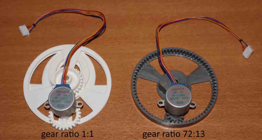
The 28BYJ-48 is a great but also very tiny stepper motor. Tiny in size and cost but unfortunately also tiny in power. Because of it's lack of power the stepper requires some additional gearing in order to overcome some unexpected friction and lifting issues of the disks. Lifting one disk and rotating one wheel can be done without problems by a 28BYJ-48 just the way it is. But lifting 13 disks is just too much for reliable operation. So when the first test run started, it became obvious that the 1:1 gearing system was not to be preferred. Although I had so many other issues, it didn't realize this at first. So the lack of power was a big disappointment as it would mean a lot of work would need to be redone. So, after careful consideration and playing with the FreeCAD involute gear settings some new hope for a decent sollution emerged. Eventually, what I came up with was a much larger gear on the cam-wheel and a much smaller cam gear on the motor. But the biggest innovation was driving the gear of the cam-wheel from the inside out. This allowed the motor to be mounted in almost exactly the same location as for the old gearing system. Which wasn't a problem at all, because the holes for mounting the motor were already allowed for a very huge tolerances due to the use of the large slotted holes in the axle+motor mounting bracket. This meant that effectively I only needed to print out two new sets of gears and swap them.
These are also the moments when you realize that the acetone gluing method is a very strong gluing method. So removing the old gear on the cam-wheel was a bit of a hassle but doable and still much faster then printing out a new cam-wheel. This whole action changed the gearing from simple 1:1 to a 72:13, meaning that the effective torque of the 28BYJ-48 motor has been increased more then 5 times. Unfortunately, this also reduced the speed of the system by the same factor. However, considering that this is to be a clock and not a fan there is no need to move very fast at all... I thought. And fortunately the resolution of the clock was already 5 minutes, so the clocks is more in a steady state than in a state where it needs to move. The photo below shows the 1:1 gear including the cam-wheel on the left and the large gear ratio gear on the right, which hasn't been glued to it's cam-wheel yet. The new setup is actually more space efficient.
 During the first tests (using a firmware setup of moving only the first 3 disks) it was noticed that the metal cover of the disk sometimes was caught by the cam-wheel. So this would result in the sound of the metal cover plate being moved sideways while the disk moved up followed by a sudden snap of the cover returning to it's home position because of the spring holding the cover in place. Now this sound was kind of nice but also annoying, as it was depending on the direction of the rotation of the cam-wheel and the smoothness of the cam of the cam-wheel combined with the exact position of the disk. In some cases it also caused the system to completely jam. Although the jamming problem could be solved with a piece of tape, it would perhaps be easier to remove the metal cover from the disk completely. Also the disks inside the system aren't going to be used anymore for storing data and the metal cover was never in sight anyway, so nobody will care or even notice it, if it is completely removed.

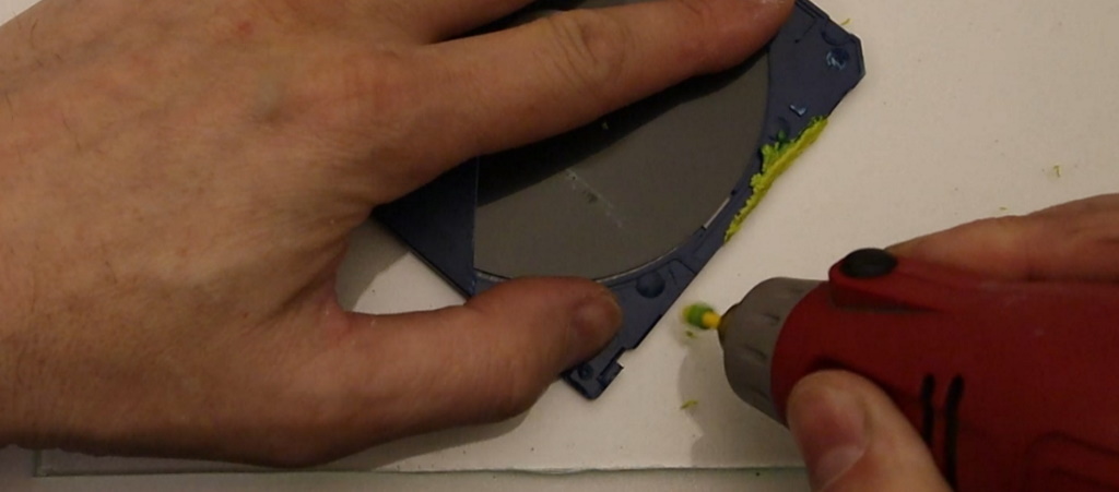
Another problem, which also is a sort of power related, was the crushing of the disks. Now crushing is a big word, but a indicates the problem nicely. It all has to do with the shape of the cam-wheel. The way the system is made is a collection of disks in a row, and 50% of the disks is just for show, they don't move at all. And the movable and non moveable disks are interleaved. This not also makes it look more solid, it also makes sure that the disks that can move are hold in place by the disks that don't. Unfortunately, the shape of the cam wheel isn't perfectly flat, sure it was printed okay, but due to acetone vapor smoothing actions and continuously handling the thin parts all caused the parts to slightly warp and bend. This causes the available disk space to vary. It becomes a problem if that space is completely occupied by a disk, which means that the cam-wheels can both press onto the disk from both sides during movement. This would mean that the disk is gently crushed by the two cam-wheels it is placed between. Now if this happens one time, the 28BYJ-48 stepper motor could handle it. But if this is happening 13 times at exactly the same time the resulting friction is just too much and the motor completely stalls. Now increasing motor power (selecting a different motor) is not really an option, simply by the fact that that would be the wrong way in solving the problem. We do not need to remove the symptom or effects of the error to make the problem go away, we need to solve the error. Now this could be solved by remove the wobble and therefor ensuring that the room for the disks doesn't change. But that's difficult as all the printed parts are very thin plastic and making them thicker is no option and increasing the space isn't an option either (who don't have the space). Perhaps we could reduce the space we need. In other words, we can also make the disks thinner. Which can be easily done by partial removal of the backside of the disk, using a knife, pliers and some scissors. So that the disk becomes smaller for the part where it interacts with the cam-wheel (and can't be seen), but has the same size and looks.
 Now this created a new problem... the edges of the disk aren't smooth... so these gaps were filled by adding plastic using a friction welding technique. Nothing more then a piece of 3D filament in a dremel and holding it against eachother when the filament is turning at a very high speed.

Proper labels:
A clock needs to indicate time, an the indicators used are this disks. Now the disks that indicate the minutes have nothing more that numbers on them, a simple number written with a thick black marker. But the labels for the hours are special, so they deserve special labels. Since these labels need to indicate a game I searched for an image of the game online (and double checked if I had the RTTTL tune to match it). And writing a name of a game with a marker looks a bit too simplistic, why not make a decent label for each of the 12 disks. Below are the labels I came up with. Printed them out in color on special printer labels I've purchased especially for this occasion. Then after printing these were laminated so that the ink wouldn't wear of and that they would look much glossier. Unfortunately... the labels I've used weren't really up to the task of sticking to the disk the way I intended (I thought I cleaned the disk properly, but perhaps not good enough for the kind of adhesive on the stickers). So eventually I ended up with adding additional glue to the labels in order to keep the on the disk. Now the experienced gamer might notice that the label from the A-team is not from a real game of the 90's, it's just a fan made 8-bit look alike image. But I liked it and since I had only 23 games and 23 tunes I needed a 24th game with corresponding tune. So I used this one, you might consider this an Easter-egg (wherein the Easter-egg is: see if you can find the game that does not exist).

Every clock can use a chime:
When a clock plays a "beep", "boing", "ting" or a complete melody at fixed times, the current time is indicated without people needing to look at the clock. And since it is a nice feature to be able to playback music, I figured that the floppy clock should also have some sort of a chime every hour. Now what would be the correct way of making a floppy clock play music. Well by playing the music of the games. But where would that music come from, you can't just play music, that would ruin the illusion of being an ordinary diskbox. So I decided to play RTTTL tunes, since that was common during the final days of the active live of the floppy disk. And I found the perfect phone to make this happen, a phone that was broken anyway, so placing a speaker inside and a display for some debugging info would also come in handy during development.
For the RTTTL tunes played back by this project, it is a simple matter of finding an RTTTL tune player routine on the web and customizing it to your own needs. And the tunes can be downloaded from various sources and tested in online RTTTL tune players. So nothing really special there. But regarding the old Nokia phone I used in the video, it was a bit more complicated. I had found a tune I wanted to enter so that I could demonstrate how people entered their ringtones back in the late 90's. So I found this tune (theme music from Indiana Jones) on the internet:
Nokia composer (tempo=125): 4e1 16f1 8g1 2c2 4d1 16e1 1f1 4g1 16a1 8b1 2f2 4a1 16b1 4c2 4d2 4e2 4e1 16f1 8g1 1c2 4d2 16e2 2f2 4g1 16g1 4e2 4d2 16g1 4e2 4d2 16g1 4f2 4e2 16d2 2c2
But now that I had a tune, how did I need to enter it into the phone. I had no manual. After some fiddling with the keys on the phone I eventually figured it out. It all comes down to the layout as shown below:
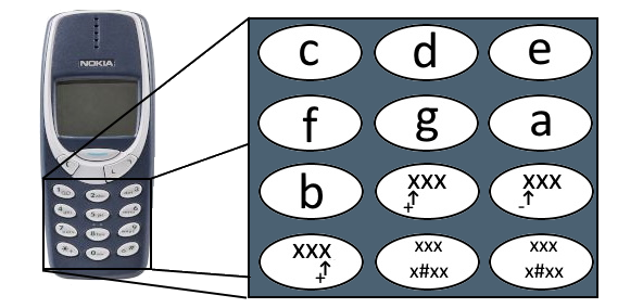 With this info it is possible to convert the tune above to a simple sequence of key presses on the Nokia 3310 keypad:
4e1    ->   3
16f1   ->   488
8g1    ->   59
2c2    ->   1*99
4d1    ->   2*88
16e1   ->   388
1f1    ->   488

4g1    ->   588
16a1   ->   688
8b1    ->   79
2f2    ->   499*
4a1    ->   688*
16b1   ->   788
4c2    ->   199*
4d2    ->   2
4e2    ->   3
The tempo value is to be entered in a different part of the composer menu, where the user can choose from a selection of possible tempo values. You might think that entering RTTTL tunes on a real Nokia phone is a bit of a hassle and it is, but with some practice the system it is very doable. But that doesn't mean I would call the composer function of that phone a practical composer. But, it does allow for the entry of tunes, which was a big deal back in those days.The floppy clock can play the following tunes: NokiaTune, Pacman, Druid, Lemmings, Magic pockets, Rick Dangerous, bomb jack, Comic Bakery, Worms, Flimbo's quest, Golden axe, Giana sisters, Krakout, Lotus esprit turbo challenge, Ghostbusters, Outrun, Popeye, Rainbow islands, Bubble Bobble, Rambo, Street rod, Back to the future, Indiana Jones, A-Team, Axel-F.
The floppy clock runs on an ESP8266 and is programmed in the Arduino environment. In order to playback RTTTL tunes the formatted code looks slightly different. All the tunes are shown below:
char *song_00 = "Pacman:d=32,o=5,b=112:32p,b,p,b6,p,f#6,p,d#6,p,b6,f#6,16p,16d#6,16p,c6,p,c7,p,g6,p,e6,p,c7,g6,16p,16e6,16p,b,p,b6,p,f#6,p,d#6,p,b6,f#6,16p,16d#6,16p,d#6,e6,f6,p,f6,f#6,g6,p,g6,g#6,a6,p,b.6";
char *song_01 = "Druid:d=4,o=5,b=80:8g.6,16a6,16a#6,16g6,c7,8a#6,16a6,16a#6,a6,g6,8p,8g.6,16a6,16a#6,16g6,c7,8a#6,16a6,16a#6,c7,d7,8p,8d.7,16d#7,16d7,16d#7,d7,8c7,16a#6,16c7,a6,g6,8p,8g.6,16a6,16a#6,16g6,c7,8a#6,16a6,16a#6,8a6,8f6,g6";
char *song_02 = "lemmings:d=4,o=5,b=140:f#6,8f#.6,16f#6,8f#.6,16e6,d6,f#6,8f#.6,16f#6,16f#.6,16g6,16f#.6,e6,f#6,8f#.6,16f#6,8f#.6,16g6,a6,1c#6,b,8b.,16b,8b.,16c#6,d6,c#6,8c#.6,16c#6,8c#.6,16d6,e6,a6,f#6,d6,a,1e6";
char *song_03 = "magicpockets:d=4,o=5,b=112:8f#6,8c#6,p,8c#6,8d#6,8c#6,8e6,8p,8d#6,16p,8c#6,16p,8c#6,8d#6,8c#6,8f#6,8c#6,p,8c#6,8d#6,8c#6,8e6,8p,8d#6,16p,8c#6,16p,8c#6,8d#6,8c#6,8a#.6,8f#.6,8c#6,8d#.6,8f#.6,8g#6,8a#.6,8f#.6,8c#6,8d#.6,8f#.6,8g#6,2a#6,8d#.6,8f#.6,8g#6,a.6,8g#6,16f#6,16d#6,c#6";
char *song_04 = "rick_d:d=4,o=5,b=160:16f#4,f#4,f#,c#.,16a#4,b4,c#,d#.,16c#,c#,g#,f.,16c#,d#,f,f#.,16f#4,f#4,f#,c#.,16a#4,b4,c#,2d#,a,p,b,p,a#4,c#,2f#4";
char *song_05 = "c64_bjack:d=4,o=5,b=225:f6,g#6,g#6,8c#7,8d#7,f7,c#7,2c#7,f6,g#6,g#6,8c#7,8f7,f7,d#7,2d#7,f6,g#6,g#6,8f7,8g#7,g#7,f#7,2f#7,g#7,f#7,f7,d#7,c#7,c7,a#6,c7,1c#7";
char *song_06 = "comicb:d=4,o=5,b=125:8g,16g,16g,16f6,16g6,16g,16g,8g,16g,16g,16f6,16g6,16g,16g,8a#,16a#,16a#,16g#6,16a#6,16a#,16a#,8f,16f,16f,16d#6,16f6,16f,16f,8g,16g,16g,16f6,16g6,16g,16g,8g,16g,16g,16f6,16g6,16g,16g,8a#,16a#,16a#,16g#6,16a#6,16a#,16a#,8c6,16c6,16c6,16a#6,16c7,16c6,16c6";
char *song_07 = "wormsong:d=4,o=5,b=112:g,a,b.,8d6,d6,8c6,8b,8a.,16g,8a,8b,2a,32p,8a.,16g,8a,8b,2e,32p,8a.,16g,8a,8b,a,8g,8a,b.,8d6,d6,8c6,8b,8a.,16g,8a,8b,2a,32p,8a.,16g,8a,8b,2e,32p,8a.,16g,8a,8b,a";
char *song_08 = "flimboq1:d=4,o=5,b=125:16c#6,16d6,16a#,16p,16a#,16p,16a#,16p,8a#,16p,16a#,8p,16a#,16p,16c#6,16d6,16a#,16p,16a#,16p,16a#,16p,8d.6,c6,8p,16c#6,16d6,16a#,16p,16a#,16p,16a#,16p,8a#,16p,16a#,8p,16a#,16p,8g,16a#,16p,8g,f.,p,16c#6,16d6,16a#,16p,16a#,16p,16a#,16p,8a#,16p,16a#,8p,16a#,16p,8d6,8c6,8a#,c6,8a#,8c6,8a#,8d6,8f6,8d6,8f6,8d6,8c6,8a#,8g,8f,8g,8a#,a#";
char *song_09 = "goldenaxe:d=4,o=5,b=112:8a4,32p,16b4,16p,2c,16p,8a4,32p,16b4,16p,2c,16p,8b4,32p,16c,16p,d,32p,8g.4,16c,16b4,2a4";
char *song_10 = "giana:d=4,o=5,b=125:8g,8g,8a,8g,8a#,8g,8a,8g,8g,8g,8c6,8g,8a#,8g,8a,8g,8g,8f,8a,8f,8a#,8f,8c6,8f,8d6,8f,8c6,8f,8a#,8f,8a,8f,8g,8d#,8a,8d#,8a#,8d#,8a,8d#,8g,8d#,8c6,8d#,8a#,8d#,8a,8d#,8f#,8d,8g,8d,8a,8d,8a#,8d,8c6,8d,8d6,8d,8a#,8d,8a,8d";
char *song_11 = "krakout:d=4,o=4,b=160:16b,16p,16b5,16p,16d#5,16p,16b5,16p,16e5,16p,16e6,16p,16e6,16p,c#5,16f6,16p,16f5,16p,16f6,16p,16f#5,16p,16f#6,16p,8f#.6,16p,16b,16p,16b5,16p,16d#5,16p,16b5,16p,16e5,16p,16e6,16p,16e6,16p,c#5,16f6,16p,16f5,16p,16f6,16p,16f#5,16p,16f#6,16p,8f#.6,16p";

char *song_12 = "lotus:d=4,o=5,b=100:16c6,16c6,16c6,8a#,8c6,16a#,8g#,8c6,8g,8a#,16c6,16c6,16c6,8a#,8c6,16a#,8g#,8c6,8g,8d#6";
char *song_13 = "gbusters:d=4,o=5,b=112:16b,16b,8d#6,8b,8c#6,8a,2p,16b,16b,16b,16b,8a,8b,2p,16b,16b,8d#6,8b,8c#6,8a,2p,16b,16b,16b,16b,8a,8c#6,8b";
char *song_14 = "outrun_magic:d=4,o=5,b=160:f6,d#6,8g#.6,f6,d#6,8c#.6,d#6,c6,2g#.,c#6,c6,8d#.6,c#6,c6,8f.,a#,16c.6,1a#,f6,d#6,8g#.6,f6,d#6,8c#.6,d#6,c6,2g#.,c#6,c6,8d#.6,c#6,c6,16f.,16g#.,c6,2a#.";
char *song_15 = "Popeye:d=4,o=5,b=140:16g.,16f.,16g.,16p,32p,16c.,16p,32p,16c.,16p,32p,16e.,16d.,16c.,16d.,16e.,16f.,g,8p,16a,16f,16a,16c6,16b,16a,16g,16a,16g,8e,16g,16g,16g,16g,8a,16b,32c6,32b,32c6,32b,32c6,32b,8c6";
char *song_16 = "rainbowislands:d=4,o=5,b=125:c,8p,c6,8p,8b.,8g,16a,8b,8c6,16p,a,8f,16g,8a,8g#.,2g,8p,16g,8f,16g,8f,16e,8d,8g,16p,e,8c,16d,8e,8f,8p,8d,16p,8e,16p,8f,16p,8f#,g";
char *song_17 = "Bubble Bobble:d=4,o=5,b=125:8a#6,8a6,8g.6,16f6,8a6,8g6,8f6,8d#6,8g6,8f6,16d#6,8d.6,f.6,16d6,16c6,8a#,8c6,8d6,8d#6,8c6,16d6,8d#.6,8f6,8f6,8g6,16a6,8g.6,8f6,8f6,8g6,8a6,8a#6,8a6,8g.6,16f6,8a6,8g6,8f6,8d#6,8g6,8f6,16d#6,8d.6,f.6,16d6,16c6,8a#,8c6,8d6,8d#6,8c6,16d6,8d#.6,8f6,8f6,8g6,16a6,8f.6,8a#.6";
char *song_18 = "Rambo:d=4,o=5,b=125:16f#4,16f#,16c#,16b4,2c#.,16a4,b4,2f#.4,16f#4,16f#,16c#,16b4,2c#.,8f#,8e.,16f#,2e.,16f#4,16f#,16c#,16b4,2c#.,16a4,b4,2f#.4,16f#4,16f#,16c#,16e,b.4,8c#,8b.4,16a4,2b4";
char *song_19 = "streetrod:d=4,o=5,b=125:16f#4,16a#4,16b4,16c#,8f#,8f#,16p,8f#,16p,16f#4,16a#4,16b4,16c#,8f#,8f#,16p,8a,16p,16f#4,16a#4,16b4,16c#,16f#,16f#,16f#,16e,16e,16e,16d#,16d#,16d#,16d,16d,16d,8c#,8c#,16p,8c#,16p,16a#4,8b4,16a#4,8f#4,16a#4,8c#,16f#4,8a#4,16c#,8f#4,16a#4,8c#,16f#4,8a#4,8c#,p,8f#4,16a#4,8c#,16f#4,8a#4,16c#,8f#4,16a#4,8c#,16f#4,8a#4,8e,16p,16e,8d#,16c#,8b4,16d#,8f#,16b4,8d#,16f#,8b4,16d#,8f#,16b4,8d#,8f#,p,8f#4,16a#4,8c#,16f#4,8a#4,16c#,8f#4,16a#4,8c#,16f#4,8a#4,8e,16p,16e,8d#,16c#";
char *song_20 = "BTTF:d=4,o=5,b=160:32p,p,8c.,16p,g,16p,16c.6,16p,a#.,16p,16a,16p,16g,16p,8a,16p,8g,16p,8f,16p,1g.,1p,g.,16p,c.,16p,2f#.,16p,32g.,32p,32a.,32p,8g,32p,8e,32p,8c,32p,f#,16p,32g.,32p,32a.,32p,8g.,32p,8d.,32p,8g.,32p,8d.6,32p,d6,16p,c#6,16p,32b.,32p,32c#.6,32p,2d6";
char *song_21 = "Indiana:d=4,o=5,b=250:e,8p,8f,8g,8p,1c6,8p.,d,8p,8e,1f,p.,g,8p,8a,8b,8p,1f6,p,a,8p,8b,2c6,2d6,2e6,e,8p,8f,8g,8p,1c6,p,d6,8p,8e6,1f.6,g,8p,8g,e.6,8p,d6,8p,8g,e.6,8p,d6,8p,8g,f.6,8p,e6,8p,8d6,2c6";
char *song_22 = "A-Team:d=8,o=5,b=125:4d#6,a#,2d#6,16p,g#,4a#,4d#.,p,16g,16a#,d#6,a#,f6,2d#6,16p,c#.6,16c6,16a#,g#.,2a#";
char *song_23 = "Axel-F:d=4,o=5,b=125:g,8a#.,16g,16p,16g,8c6,8g,8f,g,8d.6,16g,16p,16g,8d#6,8d6,8a#,8g,8d6,8g6,16g,16f,16p,16f,8d,8a#,2g,p,16f6,8d6,8c6,8a#,g,8a#.,16g,16p,16g,8c6,8g,8f,g,8d.6,16g,16p,16g,8d#6,8d6,8a#,8g,8d6,8g6,16g,16f,16p,16f,8d,8a#,2g";

char *song_100 = "outrun_splash:d=4,o=5,b=160:8d#,8a#,8d#6,8d#,8a#,8d#6,8d#,8a#,8d#6,8d#,8a#,8d#6,8d#,8a#,8d#6,8a#,8c#,8g#,8c#6,8c#,8g#,8c#6,8c#,8c#6,16c#.4,16g#.4,16c#.,16d.4,16a.4,16d.,16d#.4,16a#.4,16d#.,16e.4,16b.4,16e.,16f.4,16c.,16f.,16f#.4,16c#.,16f#.,16g.4,16d.,16g.,16g#.4,16d#.,16g#.,2c#.,8f#,32a#,b.,a#,8g#,a#,1e,32d#7,e.6,d#6,8c#6,d#6,1a#,32c6,c#6,b,2a#.,32f,16f#.,1d#,1e,32f#,32g,g#,8b,a#,g#,8f#,1d#,32f,f#,8a#,g#,1a,32c#6,d6,1c#6,8b,32c6,1c#6";
char *song_101 = "outrun_breeze:d=4,o=5,b=125:1f#,16b,16a,2g#,8a,8g#,1f#,2g#,8e,1f#,p,8a,8g#,16f#,16e,2f#,a,8b,2g#,f#,e,1f#,8a,8g#,16f#,16e,2f#,g#,8a,2b,32c6,8c#6,e6,16f#6,8a6,16g#6,16f#6,8a6,16g#6,16f#6,8a6,16g#6,16f#6,8a6,16g#6,16f#6,8a6,16g#6,16f#6,8a6,16g#6,16f#6,8a6,16g#6,16f#6,16a6,8b6,8a6,16g#6,1f#6";
char *song_102 = "flimboq:d=4,o=5,b=160:8g,8b,8p,8d6,8p,8g6,8p,e6,8c6,8p,g,8e,8f#,8g,8f#,8g,8p,8a,8p,8d6,8p,c6,8b,8a,b,8g,8d,8f#,8g,8b,8p,8d6,8p,8g6,8p,a6,8e6,8p,c6,8g,8c6,8g6,8f#6,e6,d6,f#6,g.6";

char *song_252 = "Boop:d=4,o=5,b=250:c5";
char *song_253 = "Beep:d=4,o=5,b=250:c6";
char *song_254 = "BeepBeep:d=4,o=5,b=250:c6,p,c6";
char *song_255 = "NokiaTun:d=4,o=5,b=225:8e6,8d6,f#,g#,8c#6,8b,d,e,8b,8a,c#,e,2a";
The clock in real life:
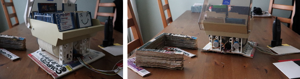
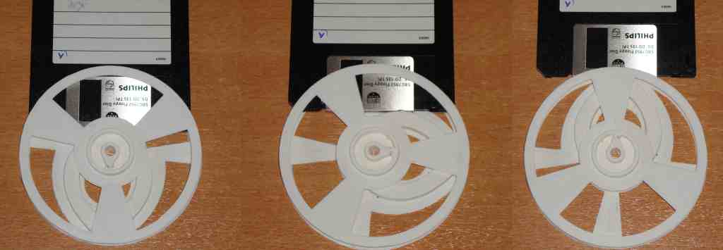
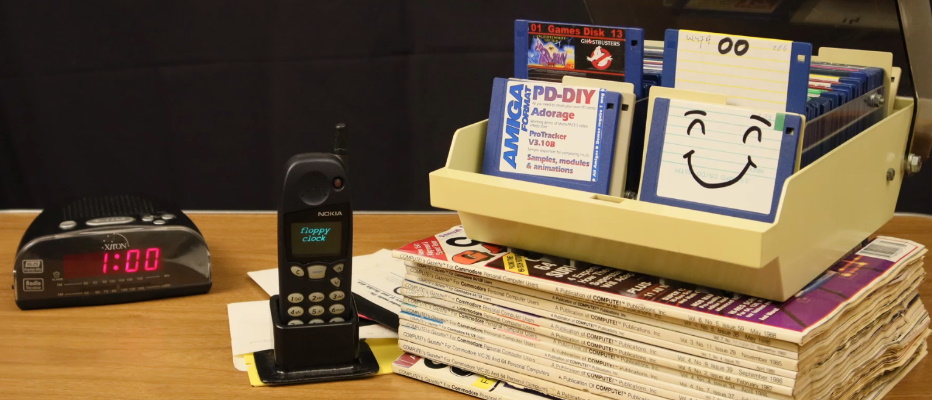
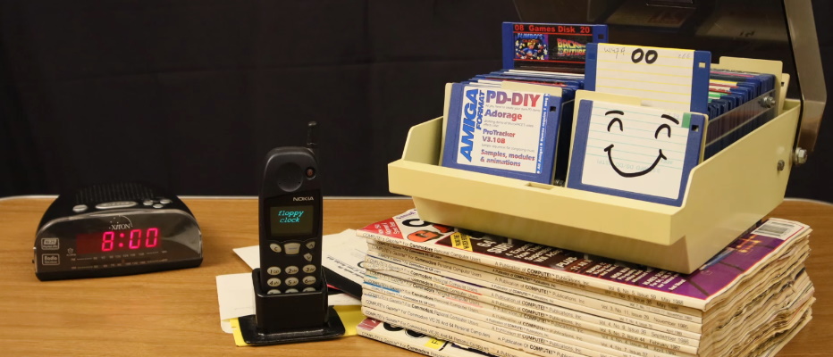
Below there are three pictures of the clock indicating 0:00, 1:00 and 8:00. These images might give you a better idea of how it looks like in action. As you can see, it's hardly noticeable at all that this is a clock. Which is perfect, goal achieved!
 At the beginning of this project (and at the beginning of this webpage) I had the idea of building a clock that was special in many ways. But in the end I realized that I've build a device that wasn't really practical. For instance the clock is really slow... making it very cumbersome to test it quickly. So debugging strange events is pretty time consuming. So technically speaking the clock isn't fully debugged or fault free.
Then there are the motors, these are heavily under powered and need to be driven at a relatively high voltage for a relatively long period of time, which heats them up significantly, but not to the point of destruction.
Mechanically, the gears are a bit warped, resulting in too much friction or being too loose (depending on the state of the rotation). A thing that can be fixed though.
The time it takes for the disk to rise is a bit too long, meaning that the clock might be a bit too slow for the first 10 minutes of every hour.
Although the stepper motors are very quit the entire mechanism isn't perfectly silent. Meaning that in a quit room you'll hear it. This gets annoying pretty quickly. At the end of the video, you'll see a shot where it is placed next to the side of the bed, this would be the worst place to have such a device, simply because the intermittent humming of the motors every 5 minutes can have the power to reduce sleep. Although it might be relaxing depending on how you are related to the project (if you are the engineer that build it or the engineers wife).
In a normal home, dust is everywhere, having a diskbox with the lid open is simply a dust trap. Now this problem and the sound problem could be solved by placing it in a glass display case, which is something I don't own, yet.
And finally the nail in the coffin of using this device continuously is reliability and energy consumption. Because of the motors moving all the time the system uses an average of about 6 watts continuously. Not a whole lot, but it adds up for something being powered all year round. And there is the reliability, I don't trust this build to be powered on 24 hours a day. I'm very afraid that things get stuck or trapped inside and will jam the system. So in other words it would require care and attention in order to prevent that from happening and to keep it running.
So to make a long story short, this device is a static piece of art, only to be powered on occasionally and for a very brief time.
Therefore I cannot recommend anybody to build this device in the same way that I did. Now, considering that I made this project for fun and as a tribute to the diskette, a storage medium that served humanity well for many decades, it is better to forget the above negative issues and focus on the functional parts and intentions of the design, which is an interesting concept. In other words, don't spoil the illusion of what could have been a perfect art-piece representing a clock.