This project is about a different way of telling time. Instead of the circular motion of the regular clock, where a day requires 24-passes around the clock, this linear clock moves in a straight line and goes up and down. It moves 12 hours up (left side of the clock) and 12 hours down (right side of the clock). By looking at one single pointer, you instantly know the exact time of the day. The clock is a very simple construction and made from MDF, a piece of M6 threaded rod a stepper motor and an ESP8266. It uses and it decorated with and lot's of brass and golden stickers. The banana is for scale purposes only and should not be placed there during normal operation.
Above are the videos I've made for my Linear clock project. One video explains why I would need another clock in my house, another shows a more explanatory video in an infomercial-like style. and a third video shows how I really build it.
Two of those videos don't tell the story how it really happened, but that's because I want my videos to be amusing and I also don't want my audience to fall asleep. The video showing the build takes much longer and is for most casual (read non-technical) viewers simply too long. The video in the infomercial-like style was made with the purpose of showing it inside the project video. Because I don't want to speak in my own videos and because I never did before, I didn't want to break the style. So I decided to make an infomercial about the project, so that in that video, I could speak. And by showing that video on the television screen in my non-speaking video the style of the main character is technically still the same. Because the main character isn't speaking, the infomercial is. I know, that is a slightly complicated way but I thought it was fun (at that moment).
Regarding the build-video I found that making a video registration of making things isn't as easy as it looks. The camera's view is constantly obscured by my own body or parts of it. Therefore drilling a simple hole becomes suddenly much more challenging because the camera angle is impossible or lighting is too weak. Anyway, for my next project I hope to do this a little bit better.
So, full of motivation, having the technology and skills... I took of on my bicycle on a trip to the local hardware store. I returned with some MDF an M6 threaded rod and some pieces of 4 mm thick and 1 meter long brass rods. Now the project was started...
The linear clock I made is very simple in mechanical design but yet very effective in creating a very different kind of clock that is very easy to read.
At the bottom of this page there is a download section where you can find the source-code of the project, the 3D files and a detailed manual describing how to use the linear clock.
In my clock I chose to have a distance between the hours of 60 mm, therefore every minute the indicator travels 1mm, which for an M6 threaded rod is exactly rotation (how convenient).
The indicator is driven by one single stepper motor, it turns left or it turns right. Now how does the indicator change from the left side of the scale to the right side of the scale when you have only one motor, you might ask. Well that is in fact very simple, although the nut inside the indicator has very little friction with the threaded rod, it is certainly not zero. Therefor when the indicator moves down the rod has to turn counter clockwise, because of the friction ,the indicator also moves counter clockwise until it can move no further, so when it moves down it rides along the PM side of the scale. And when the indicator moves up the rod has to turn clockwise and because of the friction the indicator also moves clockwise until it can move no further, so when it moves up it rides along the AM side of the scale. This way you see the indicator turn at noon and midnight from left to right and vice versa. It cannot be more simple than that, or can it? There is one catch the clock always has to be in a vertical position. Because if the clock was to be placed horizontally against the wall, then the weight of the indicator would always make it point downwards. No you could increase the friction with the threaded rod, but that would also result in much more wear on the parts, a thing that should be avoided if you want to make something that should works for a long time. So by having the clock placed vertically against the wall, the weight of the indicator is not having any effect and the clock can move smoothly without problems.
 Clock status
The top line shows the clocks status, it will indicate whether or not it is synchronized with the NTP server. And during initialization of the clock it shows the status of the indicator. Because that needs to be moved all the way to the top, to reach the home sensor and then move all the way down to the appropriate time on the time scale. Considering the clock uses M6 thread and the motor takes approx 3 seconds to rotate moves it takes a long time to home and move depending on where the clock started and how late it is (may take up to an hour or just a few minutes). Therefore all testing was preferred to be done around noon. Anyway, the status shows the number of steps remaining. During normal operation the clock doesn't need to move fast, therefore the slow motor and the huge number of steps are no problem at all.
Wifi settings
Here you must fill in your network SSID and key settings, a very convenient way of configuring. By not hard-coding these settings into the firmware it can be altered at any time using a simple smartphone or tablet. When not connected to the network, the ESP will set up its own network, and your phone/tablet can connect to that. More about this in the user manual which can be found in the download section at the bottom of this page.
Clock settings
NTP: The URL for the NTP server must be entered here, also the offset (timezone) from UTC cab be entered here. The offset setting was very useful for debugging, because it allowed me to make sure that the clock was working in the top area of the scale. Saving me lot's of time homing the device on every reset.
DST: Daylight savings time is pretty difficult to do it right, considering that there are world wide many different moments when it could take effect. So instead of writing code that almost works for everyone, I decided that it was better to make a setting to enable or disable it. When enabled an hour is added to the current time. When disabled, it is not. Although you could say that you could do that in the UTC offset, that's true, but that would be very confusing and therefore not the way to go. This way DST and timezone remain separated and all the user needs to do it change the DFST setting twice a year. Although there are rumors that it may not even be used any more in the future. Anyway, this little settings does the trick.
Alarm functionality
The alarm functionality of the clock is very simple configure, by placing an insulator along the brass sensor bar at the location of the time the alarm should sound. Though this option allows you to completely disable that alarm function. Why you may ask, well, the sensor bar is nothing but a brass bar and it may very well be possible that during the aging of the clock (in combination with poor maintenance (not keeping the brass parts of the clock nice and shiny)) the electrical contacts may be in a state where the clock constantly thinks it should sound the alarm. Which would be very annoying. Therefore disabling that functionality could be of use.
Chime functionality
The chime functionality, simply means that it sounds a small "bell" sound on the quarters of the hour. And it chimes the hours with a louder bell sound on the whole hour. Some people might find it annoying to have a clock make sounds, other finds it very comforting (people like grandfathers can appreciate this function very much, as the clock sounds like a grandfather clock).
Apply
This button must be pressed when you want the changes you've made in one of the settings, to take effect.
All settings are stored in a JSON file in the SPIFFS filesystem of the ESP8266, therefore the clock always remembers it settings even when power is lost. The clock has on the top 2 LED's and 2 speakers. The reason why I used speakers was simply because the speaker I had (both rescued from a pile of very old PC parts) were of a too low impedance (according to my liking). So by putting them in series I could double that. But the biggest advantage of these speakers were there small size which allowed me to place then directly next to the stepper motor in the top of the case. This kept all wiring to a minimum. The LED's are also 2. Both speaker an LED could have been one, but for the looks of the whole clock I liked to be the wholes and LEd's to be place symmetrically and putting them in the center wasn't possible because of the stepper-motor being so close to the lid of the case.
The LED's will indicate error situation by blinking in specific patterns, this way you know that there is a problem and you know that you must go to the configuration page to see the full description of the error. You could also memorize the blinking patterns, but that would not be very user friendly.
The speakers are used to generate sound, like chime sounds and alarm sounds (both can be enabled/disabled in the settings)
The home sensor is nothing more then a piece of brass connected to an input pin of the ESP8266, the PIN is pulled up and has some additional ESD protection. Extra ESD protection doesn't hurt in a situation were the inputs are easily touched by anyone who wants to. The home sensor is a simple piece of brass bend into the desired shape, it is round so that the indicator moving upwards will always touch it. And because the threaded rod which along the indicator travels is grounded, this would mean that when the indicator touches the home sensor it will create a logical low on the input pin. Could not be easier. The home sensor isn't exactly perpendicular to the threaded rod, this is done with a very good reason. Because if the home is reached, the indicator would be touching the home sensor, then the direction of the stepper motor changes because the indicator must move down. This would instantly result in a indicator turning towards the PM side of the scale but the home sensor could obstruct that movement if it was placed perfectly straight. By placing the home sensor under the correct angle the indicator always move freely and movement looks smooth every time when moving from AM to PM or vice versa.
The sensor bar are two bars both connected to an input of the ESP8266, again with additional ESD protection. The indicator always makes contact with these brass bars and therefore the signal on the input pin is always a logical low. The slight force caused by friction on the threaded rod makes sure that the contact between indicator and threaded rod are present. However... if the brass would corrode in a very nasty way, then electrical contact could suffer and cleaning would be required, just some gently polishing would be enough the re-establish that pretty brass shine. This is type of cleaning could be called maintenance. But maintenance is a very big word, as cleaning brass is relatively normal for things that are worth looking at. By placing insulator blocks or alarm trigger blocks on the brass sensor bars, the electrical contact could be interrupted for a short time. This could be sensed by the ESP8266 and an alarm sounds could be generated. Now the trick of determining this reliably lies is software. Because you don't want the alarm to be generated falsely. Also we don't want the alarm to be triggered on the edge of the alarm trigger block, but in the middle (more logical for the user). Therefore the software counts for how long the electrical contact is lost and if this persists for a certain amount of time, then we MUST be over a alarm trigger block and an alarm sound will be generated.
Because the brass sensor bars are very long and thin, the need some additional support, I made this out of plastic, brass would have been better. Therefore in the code I had to make an exception that no alarm sound will be generated at 06:00 and 18:00 because at those times the indicator would always be passing the supports and electrical contact will be lost. And we don't want the system to think that that lost contact is an alarm trigger. Next time, I will use conductive support material.
When an alarm is not required the alarm trigger blocks can be removed from the sensor bar, but then you could loose them. So therefore it is better to slide the 4 alarm trigger blocks out of the path of the indicator. Meaning that you slide it towards the outer edges of the sensor bar. This way the indicator will never pass them.
 Setting an alarm is as easy as sliding an alarm trigger block to the desired moment on the timeline. Normally the indicator would make electrical contact with the sensor bar. When electrical contact is lost for 3 minutes the alarm will sound. 3 minutes is exactly halve the distance of the alarm trigger block (whom are exactly 6 mm wide). Therefore the alarm time set is exactly in the center of the alarm trigger block. In this case the hole in the block would indicate the precise moment in time on the timeline where the alarm should occur. For those who look closely they might see that the alarm trigger block is just a very small P-clip. At first I tried to 3D print alarm trigger blocks myself, but I found it very difficult to print parts this tiny. So when I encountered this P-clip, I immediately saw the potential of using it in my project. The beauty of these P-clips is that the perfectly snap on onto the brass bar and they are very thin, meaning that the indicator will not hook onto the alarm trigger block and move it (or even worse, jam the whole system). If you want to make this linear clock yourself but can't find these P-clips, a simple piece of tape will do just as fine. But tape would be not very user friendly.
 If the alarm functionality isn't required, simply remove the blocks or even better, slide them all the way down to the bottom of the scale. There they will be out of range from the indicator and therefore no longer can function as alarm setting.
 Now I could have chosen to put the alarm functionality into the web-interface. But that is just no fun, also what is more user friendly, sliding a small insulator to the correct position (takes seconds) or searching for your phone or tablet, logging in to the clock web-interface, wait for the page to load, change your settings and then after a few hours wondering if you'd set the alarm, doing it all again... nope. A simple insulator along the timeline is way more effective. Perhaps not as accurate when not setting an alarm onto a whole hour, but more then accurate enough.
The design of the clock is very simple, the only thing connected to the threaded rod is a simple stepper-motor. The well known 28BYJ-48, this motor is so cheap and so well available that I will be using it in many more projects. The flat surface on both sides of the motor shaft allows very much to clamp the shaft. I made project I connected the threaded rod using a M6 spacer, drilled two small holes in it, threaded these holes with M4. This way I could insert two M4 screws to secure the motor shaft to the M6 spacer. The M6 spacer is fastened to the M6 threaded rod. Again very cheap, very easy to make and enough room for adjustment. When fastened a little nail polish could be used to secure the M4 screws, to make sure that they don't loosen over time.
 With the threaded rod secured on one end we only need a small bearing for the other end. So I used a cheap ball bearing with a hole in the middle suitable for an M6 threaded rod. I printed a ball bearing block to secure the ball bearing and screwed it all tight onto the clock. Screwed, not glued, because this way I can remove it if this may be needed (for whatever reason) in the future.
 The clock is made from MDF, a useful but boring material. So to make this look a bit more attractive I stained it with a dark color. The staining process was also surprisingly easy. The beauty of this process it is that you mustn't put it on too gently. Work rough and with large strokes. Apply the stain unevenly, this way you'd get the dark coloring and would grain effect that makes this clock look pretty. In other words, paint like in a way you normally would never paint and this time it'll look perfect.
 Because I have a brass sensor bar and brass home sensor and brass indicator the marks on the timeline, indicating the hours) should be in the same style. So I used brass nails, cut to the correct length. I first wanted to do this with a grindstone but while doing so I quickly realized that that would take too long and also would result in much error (too long or too short). I searched for a small plank (with the thickness equal to the length I required for the nails), hammered the nails into some small pre-drilled holes, and then grinding them to length using a dremel. Then I glued the cut nails into the slots I already filed into the wood and that was it. I could have done without, but I'm glad I did, because it is just a very gentle touch that makes it look so much prettier.
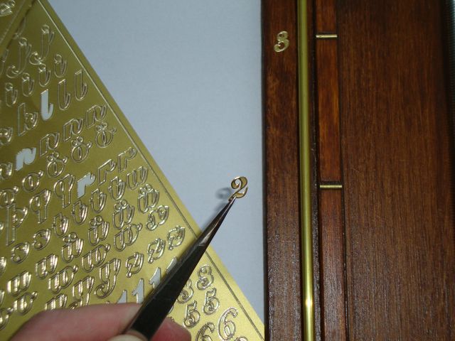
For the lettering I decided to use stickers, just like the ones my mother used to use on her X-mas cards. So I went to the shop and bought two sheets of stickers, I could not find any more at that moment and I thought I had enough with two whole sheets. What could go wrong. Well, when placing these onto the clock I soon realized that I needed much more "ones" that there were on the both sheets together. And when I realized that it would be possible that these stickers would no longer be available... I hasted to the shop, searched through the whole stock and YES there was exactly one sheet left. So this allowed me to finish my projects without weeks of delay waiting for a new batch of stickers to arrive. Lesson, learned, never guess what you need, always calculate, in this case, just count!
At first I wanted to make use of the great WiFi manager library but quickly I realized that doing that would slightly limit me in the way I wanted to visualize some settings. So I decided that I could learn more from this project if I started from scratch and write my own manager. I played with javascript and discovered that storing settings in the JSON format could have huge advantages. Considering that I've used the SPIFFS for storing the webpage, storing the setting in SPIFFS using JSON was a sensible idea. So this project learned me a lot. And with this combination some very powerful things can be realized with the ESP8266 right out of the box, no additional memory (like SD-card) needed!
The website and all the sound samples are to be stored into the 3MByte SPIFFS memory of the ESP. For those who are new to SPIFFS, some information can be found here https://github.com/esp8266/Arduino/blob/master/doc/filesystem.rst But another very informative source of information is in the form of a video from Andreas Spiess https://www.youtube.com/watch?v=jIOTzaeh7fs
For those who might want to build this project, feel free to do so, but be aware of the fact that this isn't heavily tested. It was created using the Arduino IDE in combination with the ESP8266 core 2.4.1, which apparently (as read on forums) has some stability issues. I did not investigate this heavily as my project seemed to work. But stability could suffer depending on webserver usage. Therefore if you are going to use this project, be aware of doing the heavy testing yourself. It is expected to be more stable once 2.4.2 comes out. Though considering that if your are able to build this clock and compile the code (and program the ESP) you are most likely very capable of doing the testing and possible debugging (if required). So have fun.
Also, the code could be improved by adding settings to enable disable the chime sounds for specific parts of the day. Having a clock making sounds is a fun idea... but not when that clock is in the bedroom or in the living room playing loud chime noises at the exact moment you favorite soap/show is presenting its cliffhanger.
But I have a 3D printer and I wanted the alignment of the motor and bearing to be perfect, so making it on my 3D printer saved me the trouble of measuring accurately. But was it quicker then making the parts manually, I guess not. Was the accuracy really needed, well... certainly not! The distance between the motor and the bearing is 800 mm it doesn't matter at all if the bearing is mounted one or 2 (perhaps even 10) mm of out line with the motor. But it does look better when they are perfectly aligned. Though that can be achieved perfectly fine with a hand drill and some wood. Any way, I used a 3D printer, but you don't have to, though you may if you want. The files are available in the download section.
There is one little thing that needs attention though, the support for the brass sensor bar is slightly too high, therefore the indicator might get hooked on it when going passed it. Therefore it has to be filled down a little bit to make the angles less steeps. Then the indicator can slide gently passed it without getting trapped. Minor detail, but I did not put this into the 3D design because I noticed this afterwards, just a small modification with a sharp knife and it's done.
What does this mean for those who want to build this clock, well one thing is that is isn't tested in real life. Therefore the stability of he clock's functionality (does the software crash often) hasn't been tested as much as it should. Therefore do not build this project if you are unable to hunt the code for bugs. Because I'm pretty sure there are some present (there always are, some are just not a problem
Anyway, regarding the current build that does uses M6 thread to move the indicator, that's been a bad choice, considering my programming style. Because for confirmation of what I've programmed I'd like to run my code as many times as I possibly can. Just to test and see what happens, hoping to spot a bug as soon as possible, so that I can fix it immediately. But with a stepper motor that has 4096 steps for one round and M6 thread that displaces only 1 mm per round it will take a very long time to move the indicator all the way down to the desired position in on the time line. No problem at all for a clock. But very troublesome when trying to test it... over and over again. So next time I'll think twice about my choice of parts... cheaper isn't always better. Though when the project is finished this is no longer a problem as clocks tend to move pretty slowly by default anyway..
Here are some photos of a very nice and modern looking build by Jan Bunk (bunkautomation.nl).
Two of those videos don't tell the story how it really happened, but that's because I want my videos to be amusing and I also don't want my audience to fall asleep. The video showing the build takes much longer and is for most casual (read non-technical) viewers simply too long. The video in the infomercial-like style was made with the purpose of showing it inside the project video. Because I don't want to speak in my own videos and because I never did before, I didn't want to break the style. So I decided to make an infomercial about the project, so that in that video, I could speak. And by showing that video on the television screen in my non-speaking video the style of the main character is technically still the same. Because the main character isn't speaking, the infomercial is. I know, that is a slightly complicated way but I thought it was fun (at that moment).
Regarding the build-video I found that making a video registration of making things isn't as easy as it looks. The camera's view is constantly obscured by my own body or parts of it. Therefore drilling a simple hole becomes suddenly much more challenging because the camera angle is impossible or lighting is too weak. Anyway, for my next project I hope to do this a little bit better.
The project
When the "glow in the dark" clock was finished it realized that I could relatively easily start another clock project. An idea I've had in my mind for many years... the linear clock. Now a linear clock is nothing new, but making it as simple as possible THAT is the main idea I had. So knowing how to get time from an NTP server and knowing how to make MDF look pretty I decided it was time to start this project and really finish it as quickly as possible. Because the "glow in the dark" clock has took me over 3 years, I did not want to repeat that.So, full of motivation, having the technology and skills... I took of on my bicycle on a trip to the local hardware store. I returned with some MDF an M6 threaded rod and some pieces of 4 mm thick and 1 meter long brass rods. Now the project was started...
The linear clock I made is very simple in mechanical design but yet very effective in creating a very different kind of clock that is very easy to read.
At the bottom of this page there is a download section where you can find the source-code of the project, the 3D files and a detailed manual describing how to use the linear clock.
Why a linear clock and how it works
Well the term linear might be confusing to some, because time is linear to begin with. But what linear means here is that the indicator of the clock moves in a line and not in circles. When you search the internet for a linear clock you see all sorts of devices where time is shown by moving numbers along a line, flickering LED's along a line and even versions where the hours are printed on a band that moves very slowly from left to right. What I wanted to make was a clock where all the hours of the day were visible all of the time. So that the indicator of the clock has a unique position on the timescale at any moment in time. In other words, the indicator is moving along the day, so looking at the indicator you instantly know your position in the day, so see how many time is passed and how many time is left. I could have made a clock with a huger strip of LED's to achieve the same effect, but I wanted a more old-school looking kind of clock. A real pointer and real moving parts. And by using a stepper motor and a piece of M6 threaded rod this could be achieved very cheap and very easily, so other can make it too without having to break the bank. The fun with my system is that the scale is divided into AM and PM. The indicator of the clock moves up in the morning (AM=left side of the scale) and moves down at that afternoon (PM=right side of the scale). And by doing so the clocks indicator follows the same path as the sun across our sky. Well... in theory, because of the fact we have time-zones and DST. Meaning that our local time doesn't always honor the true definition of 12:00, which would be at the moment of the sun at the highest point in the sky. But this is just a minor a detail. This makes this kind of clock very suitable to small children, as you could place notes along the timescale like (get up, breakfast, school, lunch, diner, etc). But it could very well be an aid for autistic people, because they have sometimes a very hard time in using clocks. Telling time may seem like a simple task for many of us, to some it simply doesn't make sense why time is divided in 2 circles of 12 hours with smaller circles underneath dividing those hours into 60 steps of a minute. When I come to think of it, although I understand how clocks evolved, I have difficulties accepting why I ever caught on. But that was most likely because there wasn't anything better. Anyway the linear clock has one huge advantage... it's huge. You can't make a wrist watch using the same design without loosing accuracy.In my clock I chose to have a distance between the hours of 60 mm, therefore every minute the indicator travels 1mm, which for an M6 threaded rod is exactly rotation (how convenient).
The indicator is driven by one single stepper motor, it turns left or it turns right. Now how does the indicator change from the left side of the scale to the right side of the scale when you have only one motor, you might ask. Well that is in fact very simple, although the nut inside the indicator has very little friction with the threaded rod, it is certainly not zero. Therefor when the indicator moves down the rod has to turn counter clockwise, because of the friction ,the indicator also moves counter clockwise until it can move no further, so when it moves down it rides along the PM side of the scale. And when the indicator moves up the rod has to turn clockwise and because of the friction the indicator also moves clockwise until it can move no further, so when it moves up it rides along the AM side of the scale. This way you see the indicator turn at noon and midnight from left to right and vice versa. It cannot be more simple than that, or can it? There is one catch the clock always has to be in a vertical position. Because if the clock was to be placed horizontally against the wall, then the weight of the indicator would always make it point downwards. No you could increase the friction with the threaded rod, but that would also result in much more wear on the parts, a thing that should be avoided if you want to make something that should works for a long time. So by having the clock placed vertically against the wall, the weight of the indicator is not having any effect and the clock can move smoothly without problems.
How to configure the clock
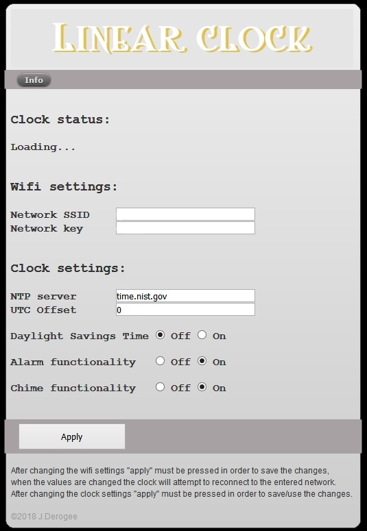
The linear clock is nothing more then a speaker, LEDs and a stepper motor connected to an ESP8266, that is contacting an NTP server every hour to synchronize it's internal clock. This means that some settings need to be done to make sure that the clock connects to your WiFi network and the correct NTP server. But also to configure the time-zone and DST setting. And don't forget the alarm and chime functions, you may want to enable/disable them too. I wanted to keep the clocks design as easy as possible. This way it is easier for people to make one themselves if they want to. Therefore no special sensors, buttons or displays. The configuration is done through a web-browser. A screenshot of the webpage served by the ESP8266 is shown below.
Clock status
The top line shows the clocks status, it will indicate whether or not it is synchronized with the NTP server. And during initialization of the clock it shows the status of the indicator. Because that needs to be moved all the way to the top, to reach the home sensor and then move all the way down to the appropriate time on the time scale. Considering the clock uses M6 thread and the motor takes approx 3 seconds to rotate moves it takes a long time to home and move depending on where the clock started and how late it is (may take up to an hour or just a few minutes). Therefore all testing was preferred to be done around noon. Anyway, the status shows the number of steps remaining. During normal operation the clock doesn't need to move fast, therefore the slow motor and the huge number of steps are no problem at all.
Wifi settings
Here you must fill in your network SSID and key settings, a very convenient way of configuring. By not hard-coding these settings into the firmware it can be altered at any time using a simple smartphone or tablet. When not connected to the network, the ESP will set up its own network, and your phone/tablet can connect to that. More about this in the user manual which can be found in the download section at the bottom of this page.
Clock settings
NTP: The URL for the NTP server must be entered here, also the offset (timezone) from UTC cab be entered here. The offset setting was very useful for debugging, because it allowed me to make sure that the clock was working in the top area of the scale. Saving me lot's of time homing the device on every reset.
DST: Daylight savings time is pretty difficult to do it right, considering that there are world wide many different moments when it could take effect. So instead of writing code that almost works for everyone, I decided that it was better to make a setting to enable or disable it. When enabled an hour is added to the current time. When disabled, it is not. Although you could say that you could do that in the UTC offset, that's true, but that would be very confusing and therefore not the way to go. This way DST and timezone remain separated and all the user needs to do it change the DFST setting twice a year. Although there are rumors that it may not even be used any more in the future. Anyway, this little settings does the trick.
Alarm functionality
The alarm functionality of the clock is very simple configure, by placing an insulator along the brass sensor bar at the location of the time the alarm should sound. Though this option allows you to completely disable that alarm function. Why you may ask, well, the sensor bar is nothing but a brass bar and it may very well be possible that during the aging of the clock (in combination with poor maintenance (not keeping the brass parts of the clock nice and shiny)) the electrical contacts may be in a state where the clock constantly thinks it should sound the alarm. Which would be very annoying. Therefore disabling that functionality could be of use.
Chime functionality
The chime functionality, simply means that it sounds a small "bell" sound on the quarters of the hour. And it chimes the hours with a louder bell sound on the whole hour. Some people might find it annoying to have a clock make sounds, other finds it very comforting (people like grandfathers can appreciate this function very much, as the clock sounds like a grandfather clock).
Apply
This button must be pressed when you want the changes you've made in one of the settings, to take effect.
All settings are stored in a JSON file in the SPIFFS filesystem of the ESP8266, therefore the clock always remembers it settings even when power is lost.
The most important parts
The clock has on the top 2 LED's and 2 speakers. The reason why I used speakers was simply because the speaker I had (both rescued from a pile of very old PC parts) were of a too low impedance (according to my liking). So by putting them in series I could double that. But the biggest advantage of these speakers were there small size which allowed me to place then directly next to the stepper motor in the top of the case. This kept all wiring to a minimum. The LED's are also 2. Both speaker an LED could have been one, but for the looks of the whole clock I liked to be the wholes and LEd's to be place symmetrically and putting them in the center wasn't possible because of the stepper-motor being so close to the lid of the case.
The LED's will indicate error situation by blinking in specific patterns, this way you know that there is a problem and you know that you must go to the configuration page to see the full description of the error. You could also memorize the blinking patterns, but that would not be very user friendly.
The speakers are used to generate sound, like chime sounds and alarm sounds (both can be enabled/disabled in the settings)
The home sensor is nothing more then a piece of brass connected to an input pin of the ESP8266, the PIN is pulled up and has some additional ESD protection. Extra ESD protection doesn't hurt in a situation were the inputs are easily touched by anyone who wants to. The home sensor is a simple piece of brass bend into the desired shape, it is round so that the indicator moving upwards will always touch it. And because the threaded rod which along the indicator travels is grounded, this would mean that when the indicator touches the home sensor it will create a logical low on the input pin. Could not be easier. The home sensor isn't exactly perpendicular to the threaded rod, this is done with a very good reason. Because if the home is reached, the indicator would be touching the home sensor, then the direction of the stepper motor changes because the indicator must move down. This would instantly result in a indicator turning towards the PM side of the scale but the home sensor could obstruct that movement if it was placed perfectly straight. By placing the home sensor under the correct angle the indicator always move freely and movement looks smooth every time when moving from AM to PM or vice versa.
The sensor bar are two bars both connected to an input of the ESP8266, again with additional ESD protection. The indicator always makes contact with these brass bars and therefore the signal on the input pin is always a logical low. The slight force caused by friction on the threaded rod makes sure that the contact between indicator and threaded rod are present. However... if the brass would corrode in a very nasty way, then electrical contact could suffer and cleaning would be required, just some gently polishing would be enough the re-establish that pretty brass shine. This is type of cleaning could be called maintenance. But maintenance is a very big word, as cleaning brass is relatively normal for things that are worth looking at. By placing insulator blocks or alarm trigger blocks on the brass sensor bars, the electrical contact could be interrupted for a short time. This could be sensed by the ESP8266 and an alarm sounds could be generated. Now the trick of determining this reliably lies is software. Because you don't want the alarm to be generated falsely. Also we don't want the alarm to be triggered on the edge of the alarm trigger block, but in the middle (more logical for the user). Therefore the software counts for how long the electrical contact is lost and if this persists for a certain amount of time, then we MUST be over a alarm trigger block and an alarm sound will be generated.
Because the brass sensor bars are very long and thin, the need some additional support, I made this out of plastic, brass would have been better. Therefore in the code I had to make an exception that no alarm sound will be generated at 06:00 and 18:00 because at those times the indicator would always be passing the supports and electrical contact will be lost. And we don't want the system to think that that lost contact is an alarm trigger. Next time, I will use conductive support material.
When an alarm is not required the alarm trigger blocks can be removed from the sensor bar, but then you could loose them. So therefore it is better to slide the 4 alarm trigger blocks out of the path of the indicator. Meaning that you slide it towards the outer edges of the sensor bar. This way the indicator will never pass them.
Construction details
The home sensor is nothing more then a bend piece of brass rod. And the indicator is nothing more then a short brass rod soldered onto a small brass pipe (actually it is a brass bushing, but that's just a very accurate brass pipe). Into that pipe I forced a modified M6 spacer. It took quite a lot of time to grind it to the correct size and forcing it into the pipe wasn't easy either but once it's in there it will never fall out. It also makes perfectly good electrical contact, which is very important considering the indicator is also a part of all sensors.
Setting an alarm is as easy as sliding an alarm trigger block to the desired moment on the timeline. Normally the indicator would make electrical contact with the sensor bar. When electrical contact is lost for 3 minutes the alarm will sound. 3 minutes is exactly halve the distance of the alarm trigger block (whom are exactly 6 mm wide). Therefore the alarm time set is exactly in the center of the alarm trigger block. In this case the hole in the block would indicate the precise moment in time on the timeline where the alarm should occur. For those who look closely they might see that the alarm trigger block is just a very small P-clip. At first I tried to 3D print alarm trigger blocks myself, but I found it very difficult to print parts this tiny. So when I encountered this P-clip, I immediately saw the potential of using it in my project. The beauty of these P-clips is that the perfectly snap on onto the brass bar and they are very thin, meaning that the indicator will not hook onto the alarm trigger block and move it (or even worse, jam the whole system). If you want to make this linear clock yourself but can't find these P-clips, a simple piece of tape will do just as fine. But tape would be not very user friendly.
If the alarm functionality isn't required, simply remove the blocks or even better, slide them all the way down to the bottom of the scale. There they will be out of range from the indicator and therefore no longer can function as alarm setting.
Now I could have chosen to put the alarm functionality into the web-interface. But that is just no fun, also what is more user friendly, sliding a small insulator to the correct position (takes seconds) or searching for your phone or tablet, logging in to the clock web-interface, wait for the page to load, change your settings and then after a few hours wondering if you'd set the alarm, doing it all again... nope. A simple insulator along the timeline is way more effective. Perhaps not as accurate when not setting an alarm onto a whole hour, but more then accurate enough.
The design of the clock is very simple, the only thing connected to the threaded rod is a simple stepper-motor. The well known 28BYJ-48, this motor is so cheap and so well available that I will be using it in many more projects. The flat surface on both sides of the motor shaft allows very much to clamp the shaft. I made project I connected the threaded rod using a M6 spacer, drilled two small holes in it, threaded these holes with M4. This way I could insert two M4 screws to secure the motor shaft to the M6 spacer. The M6 spacer is fastened to the M6 threaded rod. Again very cheap, very easy to make and enough room for adjustment. When fastened a little nail polish could be used to secure the M4 screws, to make sure that they don't loosen over time.
With the threaded rod secured on one end we only need a small bearing for the other end. So I used a cheap ball bearing with a hole in the middle suitable for an M6 threaded rod. I printed a ball bearing block to secure the ball bearing and screwed it all tight onto the clock. Screwed, not glued, because this way I can remove it if this may be needed (for whatever reason) in the future.
The clock is made from MDF, a useful but boring material. So to make this look a bit more attractive I stained it with a dark color. The staining process was also surprisingly easy. The beauty of this process it is that you mustn't put it on too gently. Work rough and with large strokes. Apply the stain unevenly, this way you'd get the dark coloring and would grain effect that makes this clock look pretty. In other words, paint like in a way you normally would never paint and this time it'll look perfect.
Because I have a brass sensor bar and brass home sensor and brass indicator the marks on the timeline, indicating the hours) should be in the same style. So I used brass nails, cut to the correct length. I first wanted to do this with a grindstone but while doing so I quickly realized that that would take too long and also would result in much error (too long or too short). I searched for a small plank (with the thickness equal to the length I required for the nails), hammered the nails into some small pre-drilled holes, and then grinding them to length using a dremel. Then I glued the cut nails into the slots I already filed into the wood and that was it. I could have done without, but I'm glad I did, because it is just a very gentle touch that makes it look so much prettier.
For the lettering I decided to use stickers, just like the ones my mother used to use on her X-mas cards. So I went to the shop and bought two sheets of stickers, I could not find any more at that moment and I thought I had enough with two whole sheets. What could go wrong. Well, when placing these onto the clock I soon realized that I needed much more "ones" that there were on the both sheets together. And when I realized that it would be possible that these stickers would no longer be available... I hasted to the shop, searched through the whole stock and YES there was exactly one sheet left. So this allowed me to finish my projects without weeks of delay waiting for a new batch of stickers to arrive. Lesson, learned, never guess what you need, always calculate, in this case, just count!
Power supply
The current drawn by the stepper motor is very low and the voltage required by the whole system is only 5V, which is used mainly for the stepper, the ESP8266 operates on 3.3V which is created from the 5V using a low dropout regulator. Where do you find a power supply that is small and supplies 5V,1A. Well currently houses all over the world are littered by these devices, the average phone charger is more then capable of supplying the power for the linear clock. So that's what I used. I do recommend choosing a high end model. Simply because the quality of the lower end supplies tend to break down relatively quick. Over the years we've had some failures. Considering a clock must be reliable, then the power supply must be reliable too, so spend a few more bucks and buy a decent one. Or you can use one from your "old" phone.Firmware
ESP8266 is a great device, cheap but powerful and a lot of examples can be found if you program it using the Arduino programming environment. So... that's what I used and it served me very well. One library I found very interesting was the audio library written by: Earle F. Philhower whom I hereby would like to thank for his efforts in sharing this with the world, Thanks Earle! Here is a link to the library: https://github.com/earlephilhower/ESP8266Audio The code also make use of the JSON library, so make sure you have that installed as well, that library is already available in your Arduino IDE, but it is not marked as "installed", so don't forget this when you want to use this project.At first I wanted to make use of the great WiFi manager library but quickly I realized that doing that would slightly limit me in the way I wanted to visualize some settings. So I decided that I could learn more from this project if I started from scratch and write my own manager. I played with javascript and discovered that storing settings in the JSON format could have huge advantages. Considering that I've used the SPIFFS for storing the webpage, storing the setting in SPIFFS using JSON was a sensible idea. So this project learned me a lot. And with this combination some very powerful things can be realized with the ESP8266 right out of the box, no additional memory (like SD-card) needed!
The website and all the sound samples are to be stored into the 3MByte SPIFFS memory of the ESP. For those who are new to SPIFFS, some information can be found here https://github.com/esp8266/Arduino/blob/master/doc/filesystem.rst But another very informative source of information is in the form of a video from Andreas Spiess https://www.youtube.com/watch?v=jIOTzaeh7fs
For those who might want to build this project, feel free to do so, but be aware of the fact that this isn't heavily tested. It was created using the Arduino IDE in combination with the ESP8266 core 2.4.1, which apparently (as read on forums) has some stability issues. I did not investigate this heavily as my project seemed to work. But stability could suffer depending on webserver usage. Therefore if you are going to use this project, be aware of doing the heavy testing yourself. It is expected to be more stable once 2.4.2 comes out. Though considering that if your are able to build this clock and compile the code (and program the ESP) you are most likely very capable of doing the testing and possible debugging (if required). So have fun.
Also, the code could be improved by adding settings to enable disable the chime sounds for specific parts of the day. Having a clock making sounds is a fun idea... but not when that clock is in the bedroom or in the living room playing loud chime noises at the exact moment you favorite soap/show is presenting its cliffhanger.
3D printed parts
Although the clock has some 3D printed parts, you can perfectly make it without having a 3D printer.But I have a 3D printer and I wanted the alignment of the motor and bearing to be perfect, so making it on my 3D printer saved me the trouble of measuring accurately. But was it quicker then making the parts manually, I guess not. Was the accuracy really needed, well... certainly not! The distance between the motor and the bearing is 800 mm it doesn't matter at all if the bearing is mounted one or 2 (perhaps even 10) mm of out line with the motor. But it does look better when they are perfectly aligned. Though that can be achieved perfectly fine with a hand drill and some wood. Any way, I used a 3D printer, but you don't have to, though you may if you want. The files are available in the download section.
There is one little thing that needs attention though, the support for the brass sensor bar is slightly too high, therefore the indicator might get hooked on it when going passed it. Therefore it has to be filled down a little bit to make the angles less steeps. Then the indicator can slide gently passed it without getting trapped. Minor detail, but I did not put this into the 3D design because I noticed this afterwards, just a small modification with a sharp knife and it's done.
User manual
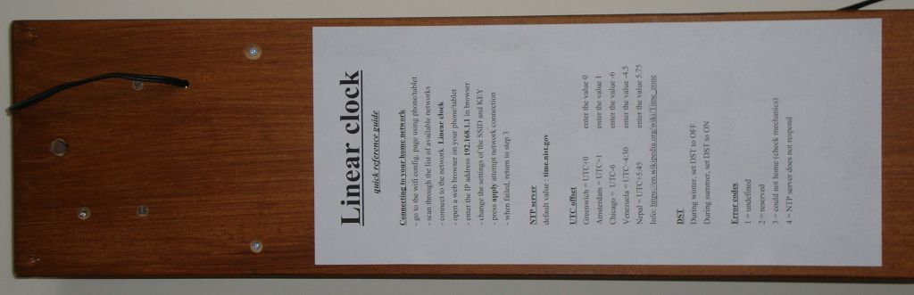
A user manual is a thing that is easily left out when doing a project. We think we will remember... but details get lost, and some day we just don't know how it works any more I made this clock with the intention that other people could also build it, so this would means that I have to make sure that they know how it works. Therefore a manual is very important. This has one huge side effect, a manual helps me in documenting the functions and features of my project. Something and the project is discarded as non functional etc. This manual is available in the download section at the bottom of this page. But we all know it... manuals get lost... therefore I also printed out some details from the manual and stuck it on the back of the clock. This way if I don't know how to change the WiFi settings anymore because I have a new router and everything changed, then all I have to do is take the clock from the wall and read the instructions on the back. This was actually the first moment I actually was happy that I made this clock in relatively large size.
Do I use actually it...
Despite of what the project video is telling you, real life is always slightly different. But that would not be fun to watch, because everybody loves a happy ending. So on the question, "do I actually use it?" the answer is "no". Although my wife said that the clock looked pretty, she also mentioned that (during testing and filming) the sounds it made were slightly annoying (and she was right). This is mostly because of the fact that the bristle I made from the brass brush is simply too hard and therefore scrapes along the metal washer. The threaded rod, slightly amplifies this sound. Although this is already solved by by replacing the hard brass brush wires with wires from a much softer (thinner wires) brush (I used a parts of the tip from a brass PCB cleaning brush). Anyway, the harm was already done and was just another point of disapproval regarding the WAF (wife acceptance factor). But there was more... because the conventional clock it would be replacing, is simply too embedded in our live(s). In fact so embedded that it is impossible to replace it by another type of clock. Although I might think this clock is an improvement in telling time... many people in my surroundings will have a different opinion. Therefore, the next time I want to build something that is WAF sensitive, I should ask first...What does this mean for those who want to build this clock, well one thing is that is isn't tested in real life. Therefore the stability of he clock's functionality (does the software crash often) hasn't been tested as much as it should. Therefore do not build this project if you are unable to hunt the code for bugs. Because I'm pretty sure there are some present (there always are, some are just not a problem
Thoughts...
This project has learned me a lot, but the thing that will stick with me for a long time it the thought that using M6 wasn't the smartest choice to be used in combination with debugging/development of the code. So I'm heavily thinking about ordering an LED strip to do a spin-off project using LED's to tell the time. Quick easy and mechanically much much easier to build. Then again, it lacks the appeal of the mechanical looking clock. But still, I'm a huge fan of LED's... so this will be a fine excuse to buy a long strip of them.Anyway, regarding the current build that does uses M6 thread to move the indicator, that's been a bad choice, considering my programming style. Because for confirmation of what I've programmed I'd like to run my code as many times as I possibly can. Just to test and see what happens, hoping to spot a bug as soon as possible, so that I can fix it immediately. But with a stepper motor that has 4096 steps for one round and M6 thread that displaces only 1 mm per round it will take a very long time to move the indicator all the way down to the desired position in on the time line. No problem at all for a clock. But very troublesome when trying to test it... over and over again. So next time I'll think twice about my choice of parts... cheaper isn't always better. Though when the project is finished this is no longer a problem as clocks tend to move pretty slowly by default anyway..
Downloads
Everything you need regarding this project is stored on my GitHub page: https://github.com/JanDerogee/linear_clockSimilar builds by other people
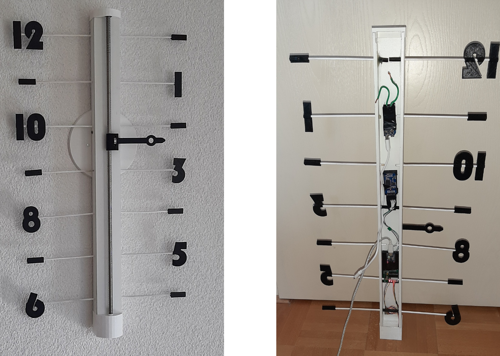
The linear clock you see on this page, has inspired others to build a linear clock according to same mechanical design concept. And if you have build such a clock according to the same concept, feel free to let me know and your build will be displayed here too.Here are some photos of a very nice and modern looking build by Jan Bunk (bunkautomation.nl).