 This page shows the prototype of the lighthammer, a lightpen-type device for use with a CRT monitor. With this device games using the lightpen/lightgun technology get a slightly different twist. Allowing for more interaction between the game, the screen and the player. Unfortunately, it's only 30 years too late.
How it is constructed
The"hit detection" sensor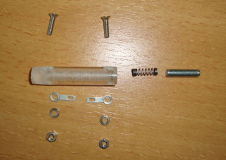
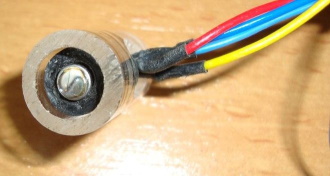
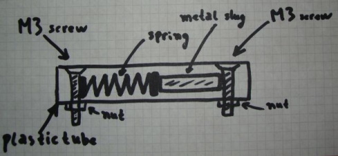 The hit detection sensor could have been made with an MEMS acceleration sensor and an Arduino, but there really is no need. As this would make it too big to fit into the hammer and way too complex. And I didn't want to make it complicated as it must be easy for others to build. Therefore the design below is much simpler and can be made with parts lying around. It can be made by everyone who is capable of holding a soldering iron (on the proper end). It consists of a metal slug (which is nothing more then an ordinary nail cut to the desired length). This nail is iron and therefore relatively heavy. Which is perfect because this results in more force when the sensor hits something. The slug is inserted into a plastic tube (I made it from a piece of plastic rod rescued from the waste bin. I drilled a hole and converted it into a tube, which a hole the perfect size to house the metal slug). Along with a small spring (the tube and the spring could both be taken from an old ballpoint pen). Two small M3 screws function as contacts. Using two small soldering eyes two wires can be connected (but this is not really required, because you can also wind the wire directly around the screw if you like to). The spring has to be adjusted to the proper force, because it has to push the metal slug (with little force) against the other screw. The spring and the metal slug will now create an electrical contact between the two screws.
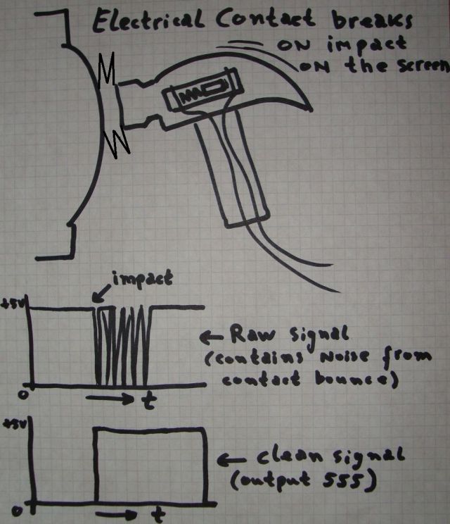
 When the assembled sensor travels to the left and suddenly stops (due to a hit on a screen for example), then the metal slug will continue to travel in that direction because of its mass. While doing so, it will break the electrical contact between the two screws. A fraction of a second later, the spring has slowed down the slug and it will push the slug back to its original position and the electrical contact is restored. The sensor is sensitive in one direction (actually 2), perfect for our application. The sensor, in fact, is nothing more then a "normally closed" switch. When the sensor hits something the slug will continue traveling and breaks the contact. The spring will eventually return the slug and contact will be made. But when the slug returns, it bounces a many times before it come to a complete standstill. This is normal, it happens in every switch no matter it's size or mass. The only difference is the frequency of the bouncing effect. The higher the mass, the lower the bouncing frequency. Anyway, this means that this switch will generate multiple pulses. But this is not the whole problem, the pulses are too narrow for the C64 to detect reliably. So we must stretch these pulses. A simple task for the trusty 555 timer. The whole electronic circuit can be easily build onto a small piece of prototyping board. Not only helps this to get rid of the multiple pulses, it also stretches the pulse to a minimal duration which makes it much easier to detect. The circuit is very easy to build, it requires a 555 and only 6 extra components. The transistor may be of any NPN type you can find, this is not critical because the voltages and currents that it must control are very low.
The light sensor
 The easiest way is to use a special sensor is an OPL800-OC (Datasheet of OPL800-OC) this is still (2015) a widely available sensor (Digikey, Mouser). The beauty of this sensor is that it holds an internal amplifier, which makes using it very easy (because we do not need to add any other component). I chose the OC type (which stands for "open collector"). If I use the type with a push pull output then this will cause problems in combination with the keyboard and to solve this a series diode has to be added to the output of the sensor. You can find more information about how to fix this on the lightgun page of my website.
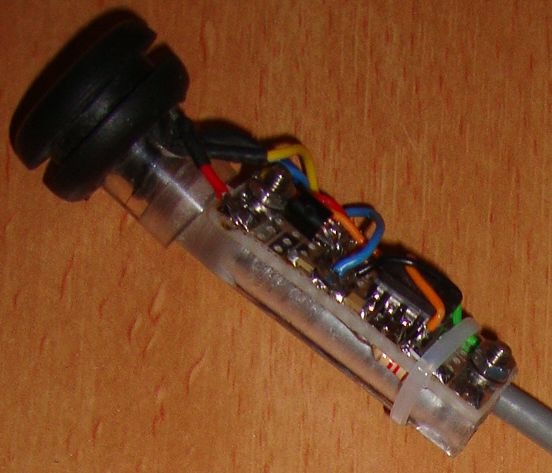 In the image shown you'll see the sensor mounted using a small rubber ring inside a plastic tube. This plastic tube is big enough to fit onto of the plastic tube of the "hit sensor". I designed it this way so I could play around with both individual parts during the testing stage. You'll see how the two plastic parts meet in the image below (right). But for the final design this isn't required at all, in fact it only makes it too complicated. So if you want to build your own lighthammer, you'd better combine the two into a single piece of plastic tube.
The lighthammer assembly
The original hammer is a simple "rubber" pet toy (not a toy for rubber pets, but a toy made of "rubber" for a pet (no not the computer), most likely a dog although there was no label on it so how can I be sure). Anyway it makes a squeaky sound when you squeeze it. Although it also exists in a black version (which I found out later). I bought the grey version at a high discount at the local supermarket, the costs were so low that I wondered if they were even new ;-) But considering the number of these toys they had (back then), I was sure that they were new.
The first thing that we (need) to do is to remove the whistle. And at the back we make a small hole for the cable and in the front of the head of the hammer a hole for the sensor. To prevent the hammer from hitting the screen too hard, some additional rubber (a cheap grommet) might be added, this way we can keep the sensor very close to the screen but don't have to worry about damaging the lens of the sensor or the CRT screen.
assembled.gif)
 The games are written for the lighthammer... but considering that not many people will own a lighthammer but do own a lightgun (see my lightgun page for more details) I've made the games lightgun compatible. You can use them with a Stack light rifle of Magnum light phaser compatible lightgun. This way I've just added two games to the very small library of C64 lightgun games. In order to encourage the development of new lightgun games I've made the source-code of my games available. And hopefully people will write a new lightgun or lighthammer game.
How to build the circuitry again... (and better)
I've done this little project for fun, and in order to maximize the fun I intended showing it on the Commodore meeting in Maarssen on June 20, 2015. But during construction of the 90 deg. angled 9-pole sub-d connector, the most common error of all happened to me. And since it hasn't happened for a long time, it was due to happen, yes, I swapped the polarity of the power wires. My sleepy head in combination with my arrogance (I figured I did not need to check my own work) made me pay the price, I fried the circuitry of the hammer! At first I thought it didn't work for other reasons, but after a minute I realized that it was something serious. Because smoke began to emerge from the tip of the hammer. The magic blue smoke. That was one of these days that you realize that big powerful power supplies aren't always a blessing. Well, I still had 3 weeks to solve this problem (because of the already scheduled demonstration).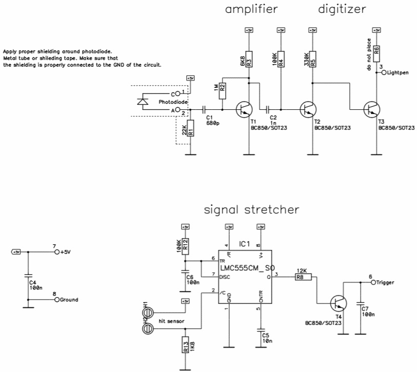 So this allows me to repair it and while doing so... improving the design. Although there is nothing wrong with prototyping board, it doesn't allow an easy modification or major repair. So time to make a tiny PCB. Unfortunately the sensor OPL800-OC wasn't available on such a short notice, so I must come up with an alternative. Which is not a big problem because I can re-use the design of the 3-in-1-gun. This design is simple in the fact that it uses more easy obtainable parts. The sensor can be almost any photo-diode (as long as it is sensitive to anything between red and blue, don't use an IR-only photo-diode). I used the SFH213, is comes in a 5 mm LED like shape so it is easy to handle. It also has a large lens which helps regarding light sensitivity. However this simplicity comes at a price, the circuit itself has more components, but, thanks to the power of SMD the total circuit is not larger then the original prototype. The new circuit is even more sensitive then the prototype (although that wasn't an issue).
The resulting is a much cleaner design as shown below. I'm very pleased with the new design, it is much more compact and it gives me a better feeling, knowing that this circuit will be experiencing many hits over it's lifetime. So a proper printed circuit board is easier to inspect whenever it might fail. Although I'm sure that a properly build prototyping board can work just as reliable.
 When I tested this circuit I noticed that I was encountering a lot of interference. And that wasn't that strange, we are making a sensitive circuit with lot's of gain and we are holding that against a CRT that uses strong magnetic and electric fields. Fortunately there is an easy fix. It is called shielding and can be done very cheaply. I used aluminum tape, wrapped that around the sensor tube and while wrapping the tape I added some grounded wire, this makes contact with the tape so the tape is now connected to ground. Better was to use copper tape because to that you can solder the wires (more reliable connection). I could have used some copper tubing, but in this case the weight of that would not be a good idea.