Why this project?
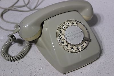 I grew up in the 80's and the telephone we used for over four decades was a simple rotary dial phone... Now, some may call me an idiot, but it took me over 40 years to realize that that "simple" mechanical mechanism (that mass produced and highly reliable piece of clockwork) has served humanity very well. As without it the telephone revolution (connecting the world through wires) would not have been possible. Simply because a telephone system, that requires an operator (as it did before the dial system was invented), would have it's practical limits and would therefore prevent further expansion of the telephone system. Because the dial mechanism contributed in the elimination of a human (the telephone operator) making the physical connections on request by the caller. The main importance of the dial mechanism is that it can be made relatively easy, cheap and reliable all due to it's "simple" concept and construction. Some very crucial factors because it had to be put into every possible telephone. Now I'm aware of the fact that much more components are required in order to build a global telephone network, but the dial mechanism (since it needed to be in every phone) was perhaps the most crucial one.
The simplicity of a small wheel producing pulses and another system made from an electromagnet and wheel with switches without any active elements, very much appeals tome. Especially today as electronics are everywhere and we almost seem to forget that you can do a lot without it. Reaching for an 555 or an Arduino is quickly done, but when you put your mind to it things can be solved differently and in a more old fashioned way which most of the times is much more fun to see it working. Because things that turn, move, make sounds, and allow you to physically tinker with, just fascinate me. Therefore you may say that this project is partially about KISS (not the band, I mean "Keep It Simple, Stupid") but mostly about making an ode to the dial mechanism.
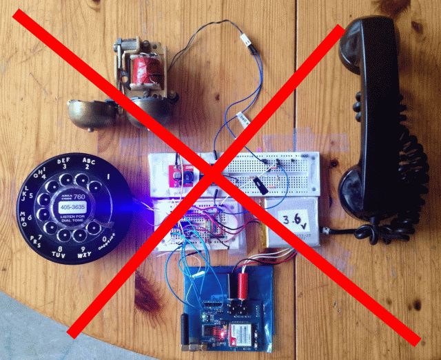
Although there are still plenty of phones with rotary dial mechanisms to be found, destroying an old phone to retrieve the mechanism and do something with it just doesn't feel good. So It breaks my heart when people destroy a perfectly fine old phone in order to realize their project.Therefore, as shown in the image below, I will never do such a terrible thing. The photo below was found on the internet and does not belong to me or any of my projects. But to be honest... (since I don't have an old rotary dial phone) that's easy for me to say as I'm not in the position to do so. And chances are that if I had such a phone, I most likely had taken the shortcut of "borrowing" the mechanism.Fortunately perhaps, because now the world has a more modern version of a the dial mechanism, a version anyone with access to a 3D printer should be able to build as you don't have to be a clock maker or search for obsolete or difficult parts.
More about the project itself
So now I was asking myself "wouldn't it be possible to make such a mechanism with a 3D printer,sure, but how to keep it simple, how to prevent using parts that are difficult to obtain". I want to make a design that anybody all over the world can make. A simple DC motor instead of a spring perhaps, a camwheel and some micro=switches? But the most important thing perhaps is that it must feel like an old rotary dial. It should gracefully turn back to the idle position at the exact same moment the user releases the dialplate. And it should only generate pulses when the dial is returning to the idle position. And without the use of modern electronics. Preferably, semiconductors are completely to be avoided.Just imagine a youngster making such dial mechanisms, just for the fun of it, making project that operate like things did more then 100 years ago, now wouldn't that be fun? It sure would be a great learning experience for a new generation that never seen a rotary dial mechanism in real life. Perhaps only therefore it could be a great project for schools.
 I did try to find such a mechanism on the internet, but failed, apparently this is isn't a thing (yet). I did find a 3D printed dialplate with a 3D printed string attached to it, but there was no speed regulation of any kind, so it would turn back as fast as it would go. But 3D printed springs are not really suited for the task, they are under powered and depending on how they are printed, too stiff, too loose or too brittle. Also the requirement for generating pulses when returning to the idle position wasn't honored as it only had an optical slotted disc. Though with two optic sensors (with a 90 degpahse difference, just like in an old ball mouse) that could be solved in software. But to be honest, I want a simple system without electronics.
At first I thought I should not make it too difficult for myself, so I briefly thought about a system with a stepper-motor, completely controlled by a small microcontroller, but it felt wrong how I needed to detect the user from releasing the dialplate. But mostly it also felt wrong that the design would be (from a technological standpoint) overly complex.Because, well, a microcontroller and stepper-motor, that's space age technology, while all I want to do is make a simple dial. They did it with clockwork back then, so I should be able to make it without electronics now.Otherwise I would not be true to the concept of a mechanical dial, or would I?
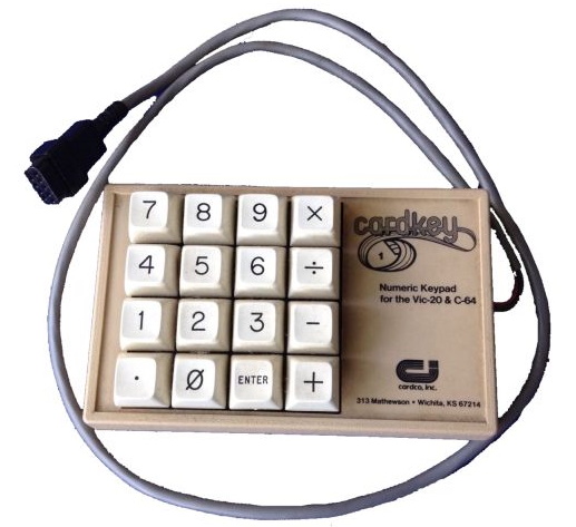
So I decided to recreate a dial mechanism using no electronics at all, but what would I eventually would like to do with it? Hmm... as I needed a showcase to demonstrate it, I imagined that it had to be something ridiculous,something that would make no sense at all. Hmm...what could that be? Now it also happens to be the case that I like retro-computers, like the C64 and VIC20. So perhaps I could interface it to these systems, but for what? Well, typing in data from magazines was something many youngsters did 30 years ago, so I did that too. And it annoyed me that the data statements had lot's of numbers and that I had no numerical keyboard on my C64, while the C128 did (but I could not afford one). Sure, there existed joystick port based keypads but I never found them in my local shop, however if I did found them I most likely would have found them to be to expensive and would not have bought it anyway, considering I was saving up for a disk drive... floppy discs... a printer... What if I could make a numpad with a rotary dial, now that would be "sort of" usable... not practical though as it would only take longer to input data that way... PERFECT! that's exactly the most useless application I can think of, and it fit's my YouTube channel perfectly which is full of retro related projects. Wahoo!! We have a project!
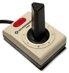
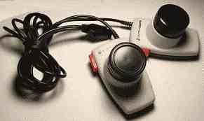 So how should it look like the? Well the last project (rotary joystick) didn't look well on camera at all, so my new project must be made with contrast rich colors. The old Commodore joysticks(which were terrible to use) were mostly white with a black stick and a red button and a black bottom. I would not call them pretty, but great contrast. Some may call this joystick design ugly, but they need to see this through the eyes of a Commodore designer more then 3 decades ago. The VIC-20 was white, the PET computers were white, so making the joystick white made sense. I think that the stick was black because it wouldn't stay white for a long time anyway as that would become dirty very quickly in the palms of those sweaty little gamers they were trying to sell it to. But the red fire certainly button looked great.The paddles were more friendly for the user, but paddles aren't as common as joysticks but that's a different story...
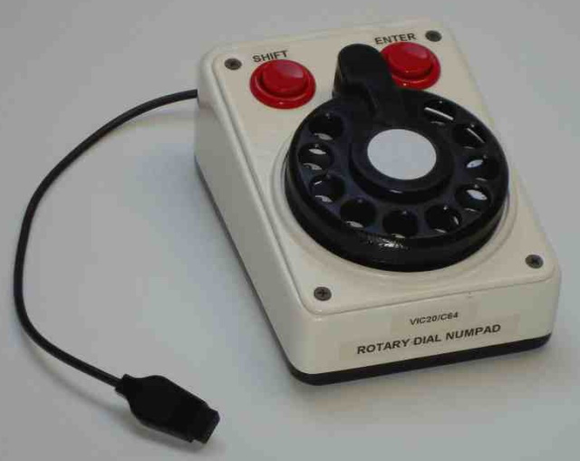
The rotary keypad I wanted to make should be placed right next to theVIC-20. Therefore shape and height were determined by the VIC-20, so that it would look like it could have existed back in the days. But we all know, that would not have made any sense back then as that it does now.Although at first I wanted this to be a C64 project, but since the color scheme made it work better with a VIC-20 I took a turn in that direction. But considering it could work on both, I simply wrote a driver for both systems. And just for the fun of it I also wrote a program that could make the C64's SID chip produce some DTMF signals, so that I could dial DTMF tones with the rotary dial connected to the joystick port of my C64... useless I know, but so much fun and not very difficult to do. So here below you see a picture of the end result of my little project. As you can see it has the color style to match the other VIC-20 input devices.
 So that's about how this project evolved, I started with a simple idea but it has the potential of interesting a whole new generation to the power of the rotary dial. I have connected it up to my retro computer. But for those who also want to make one, there is no reason not to connect it to your Arduino and there is no reason not to build your own stepper switch or Strowger relay system (although that would be significantly more work) it would be a joy to see it operate. And to be honest, I hope to build a simple stepper relay, just to complement the rotary dial design, the main problem is, is that I like so many other things too, ahhh priorities, priorities...
For those who wonder, about connecting a real phone directly to the joystickport without opening it up or removing the mechanism, that would be possible. As the driver software I wrote certainly would be able to process the signals. However a phone contains all sorts of coils, switches and parts that could induce voltage spikes if driven/used in the wrong way,I would not recommended connecting any old phone directly to your joystick port without knowing exactly what's in the phone. Simply because I don't want any voltage spikes to be induced to those CMOS inputs of the old computer. Fortunately, since I have no such phone, In ever was tempted to try it anyway. But theoretically it should work the same way.
How does it work?
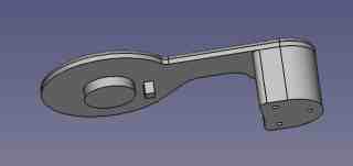
Normally a rotary dial works like a simplified clockwork. With a full or partial turn of the dial plate a spring is wound,this spring allows to be unwind when the dial plate is released. The beauty of the design lies in the fact that the winding is unrestricted in speed (you can turn/wind it as fast as you like) but when you release the dial plate it always returns to its idle position with a very accurate speed. Because when the dialplate rotates towards the idle position, the regulator mechanism is engaged and controls it speed.Now my 3D printed design does not have such fancy clockwork, it does not even have a spring. The reason is that clockwork and springs are difficult to print or to easily obtain. So in order to return the dial back towards the idle position, I use an simple electric motor. A geared motor and the cheapest geared motor that is commonly available all over the world is the standard RC hobby servo. Its been made for decades and its size is very well defined. Below a quick sketch of the mechanism and how it's put together. I apologize for my poor drawing skills.
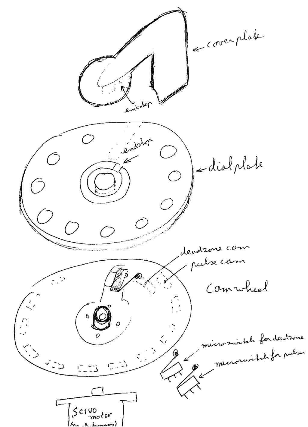 The motor is to be engaged ONLY when the user releases its finger from the dial plate. The motor is directly connected to a camwheel, the camwheel is coupled to the dialplate simply by pushing against it. On the location where diaplate and camwheel meet, there is a micro-switch, so when the user turns the dialplate, the micro-switch is pressed and the motor is no longer powered, when the user releases the dialplate,the spring of the micro-switch forces the dialplate back for a few mm, then the motor is engaged and the camwheel turns towards the idle position untill the endstop of the dialplate hits the ridge in the endstop ridge in the faceplate, then then dialplate is forced to push against the micro-switch, which breaks contact en the motor stops.
Unfortunately, when everything runs very smoothly (the way we all like it) an issue of oscillation arises, as the micro-switch spring pushes to motor away from the endstop activating the motor again. So in order to prevent that situation another micro-switch is used to create a deadzone, an area where the motor is shutdown before it reaches the mechanical endstop. Creating a stable situation for even the mechanically smoothest mechanism.
Because the motor is turned on as soon as the user releases the dial we can uses this to also power the switch that creates the pulses. Because we only want to generate the pulses when the camwheel rotates back towards the idle position.
 To prevent pulling too much power from the joystick port, I power the whole system with a set of AA batteries, which is no big dealas these only need to power the motor when the dial plate is released and need to turn back to the idle position, so the batteries are completely disconnected when the device is not used.
Safety first: although I could make a hard connection from the pulse micro-switch to the input of the retro computer, I do no wish to do that. Simply because I fear that a battery voltage that is too high might damage the input, or too low and it will be unreliable. But also because I'm afraid that the motor may create high voltage pulses (as some DC motors seem to spark quite much even at low voltages). So to prevent these possible high voltage from damaging the inputs of the my retro-computer a galvanically isolated system is created using a small relay. I chose a tiny relay as it would meet my design requirements of no electronics (or "no semi conductors" to be more precise) but an optocoupler would have done the trick just as well. Technically speaking you can work around this BUT adding an optocoupler or a simple relays works in all situations and since I want other people to be able to rebuild this project and to keep it all simple and understandable, it seemed like the most appropriate sollution. As I don't want people to rebuild this and blow up their joystick port because of a simple wiring mistake.
Servomotor modifications
The servo motor isn't used as a servomotor at all, it is used for it's gears and it's motor only. The electronics are to be completely removed. Also the end-stop inside the servo needs to be removed so that it can rotate continuously. There is a great tutorial showing how to do these things, so I would like to refer to that. https://www.instructables.com/id/How-to-modify-a-servo-motor-for-continuous-rotatioThe most important pictures from that website related to this project are shown below, but I would like to encourage you to also visit the instructables website to get some details of the procedure. Anyway, for THIS build, you do no need any electronics at all, just the bare motor and the geartrain is all we need. Make sure that you don't forget to remove the potentiometer as this also limits its movement. The potentiometer is located directly under the axle gear connected but not shown in any of the pictures below.
 As shown in the picture above, the red wire is soldered to the pin next to the red dot on the motor. However, the turning direction of the motor may be different then what we need, so perhaps in you situation you may need to solder the black wire to that pin. In other words... if it doesn't work like you expect, swap the wires. Therefore it is best to try this all out with a low voltage setting on your power supply when you first test this out. The turning direction we want is that the axle of the servo rotates in the Counter ClockWise direction when power is applied to the motor.
The 3D printed parts
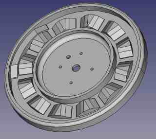
The build consists of five 3D printed parts, which are shown below. All parts are designed in such a way that printing should not require any support material at all. The first part is the baseplate (used to mount the motor and the two micro-switches that ride along the cams).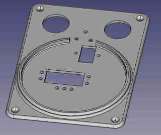 The camwheel, this wheel contains the cams used for the pulses and for the definition of the deadzone area. The deadzone area (the single and large cam on camwheel) is required to prevent oscillation of the system, depending on the power applied/the smoothness of the servomotor you may want to adjust the size of this cam with dremel. The side shown in the image below is the bottom side.
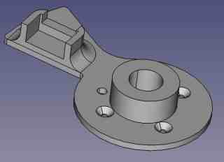
 The camwheel_switch_plate (required for mounting the micro-switch to the topside of the camwheel). This could have been integrated into the camwheel design, however by having two seperate items, the whole is easier to print (because now the camwheel is completely flat on one side). But also to allow me to tweak the design in case a design error was made, so that would save me from printing the entire camwheel over and over again. The camwheel_switch_plate also acts as the bottom halve of a low cost axle/bearing/support for the dialplate to move on. This part is to be screwed onto the camwheel with short and sunken M3 screws at first, then (when you know it all works like it should) you must glue it securely to the camwheel by adding some drops of superglue (PLA) or acetone (ABS).
 The dialplate (this is actually what it's all about)
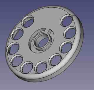 The coverplate, this parts functions as a coverplate so you don't see the screw of the servomotors axle. But more importantly, it acts as the endstop for the dialplate so that it can only rotate 355 degrees and knows when to stop turning. And last but not least, the coverplate also acts as the top halve of a low cost axle/bearing/support for the dialplate to move on. This add to make it all feel a little more rigid (or less wobbly as some may say). For smooth operation this part could be slightly lubricated with silicone grease, but it's not really required, unless you are planning some heavy usage.
Design problems
When I've build my first prototype I imagined this to be a project I could do in a jiffy... how wrong could I be! Very wrong and all mistakes you can imagine, I made them. The main problem was that the micro-switches have a very small weel attached to the tip of the lever. This wheel is to ride along the track of the camwheel and has to move up and with the cams. At first I envisioned this to be a problem, so I decided to make the cams on the side of the camwheel (in the horizontal plane). This however made it difficult to assemble as you can easily bend the lever when pushing all parts together. But also tuning the location of the micro-switch is difficult as there is no way to reach the switch as it is covered by the camwheel. I wanted the micro-switch to be on this location to prevent problems due to height variations of a wobbly camwheel. But in the end it was no big deal anyway and the cams were moved in the vertical plane and the micro-switches were mounted underneath the baseplate. This allowed for moving the micro-switches up and down by adding or removing washers were needed. It also allowed for a lower build height as the micro-switches would no longer needed to be placed entirely under the camwheel. In the end it allowed me so add another micro-switch to add a deadzone.Oscillation, was a big problem, the spring that made the dial plate return to it's on/off position also pushed the camwheel away from the idle position, activating the switch and turning on the motor... until it hit the end-stop where it was turned off... until the spring of the micro-switch pushed it away from the end-stop and tuned the motor back on... and so it merrily oscillated in the vicinity of the endstop, making all sorts of nasty noises but most of all, look like rubbish.For weeks and weeks I tried to come up with a sollution to solve this as simple as possible. I tried adding grease to the servo geartrain to dampen movement... bad idea as it would make turning the servo by hand much more difficult. I tried adding diodes and capacitors to keep the motor on slightly longer, but that didn't work satisfactory. Also that didn't feel good as it would no longer result in a construction that uses no electronics. I tried to come up with a ratchet construction (to allow the motor to apply force in only one direction) but that proved to be impossible as the forces for the turning direction do simply not allow this to work. in other words, the ratchet would simply never couple because the dial plate relative to the camwheel always turn in the same direction. I found out that lowering the motor voltage reduced the effect to an acceptable level where the oscillation stopped after a few bounces to the end-stop. But that didn't feel like a good sollution as it would be different from build to build. But also because it reduced the operating speed of the dial. Making it less/realistic to use.
Then I realized I could solve it with another micro-switch, if I would allow an error or deadzone to exists around the endstop. Stopping the motor before hitting the endstop would prevent the spring of the micro-switch from being pushed and would prevent the camwheel from turning back dueto those forces. In the end it was all so simple, adding a deadzone, a certain area where the system no longer actively regulates it's movements. And this deadzone was to be defined by a second track on the camwheel.
One tiny little detail is the wiring, which was mostly caused by the fact that I had only one joystick cable I was willing to cut up. It was a faulty cable, that broke at the joystick side, but when shortened I could use it for other things... well not many things as the cable was too short for most applications, but it fitted this project perfectly.In order to connect all the wires and have some strain relief, I soldered the wires to a small piece of circuitboard. From there the other wires were connected, this way I could easily make modifications and did not have to worry about damaging the cable even further. The micro-switches and their wires are also soldered to a piece of circuitboard, so I could easily make modifications if needed (in case I made a wiring mistake) and/or adjust the height of the micro-switches rolling over the cams of the camwheel. The relay for galvanic isolation between the motor and the CBM computer makes it looks a little bulky. So now the device looks like a mess of wires and PCBs while in essence the whole circuit does not need to be any bigger then a motor and 3 switches. So I feel like I screwed up making some very simple looksrather difficult in the end.
Design itterations
Now like most... correction... ALL of the things I create... it wasn't right the first time. Below is a picture of the various prototypes I made before my project finished a state where I was able to accept the performance of the design as "good enough". The final design still isn't perfect from my personal point of view,simply because there are some points (see pros and cons below) I would like to improve on. But from a practical point of view I realized that it was time to stop tinkering and come to my senses, simply because things do not always need to be perfect. Remember that in most cases "good" is more then "good enough". Because, well for the project I'm making (a VIC-20 / C64 numpad) who cares if it is 2 mm flatter or super slick perhaps the contrary, the bulky look may even add to it's appeal or silliness of the entire concept.
Design pros and cons
Like any other project, this project has its pros and cons. The big pros are: Can be made by anybody that can hold a screwdriver and operate a 3D printer (you don't have to be a clock maker to complete this project). No electronics required.The cons are: One of the micro-switches is connected via a wire that moves along with the rotating parts, this is a potential failure point. However it is easy to repair and when it fails things do run out of control, the motor simply stops, so it's not perfect but it's certainly is not unsafe for the operator or the mechanical construction. The speed of this system, the pulse duration isn't very accurate. As it mainly relies on the load of the system and battery voltage. However there is a way to compensate for that using a simple electronic circuit. Fortunately,speed accuracy within a 5% band isn't required for many applications. This design was never intended to replace a real dial mechanism so that doens't really matter, the C64 and VIC20 software drivers simply count pulses and have a generous timeout so they will almost accept any kind of signal, it even works moving the joystick up for 8 times and register that as an 8. The trick to accept a wide variety of pulses is simply to have a large enough timeout, the only downfall is that a large timeout make the system seems to feel a bit slow as it need to expire the entire timeout before the last pulse is accepted as the last pulse. The camwheel switch plate is rather thick, it could be reduced by at least 2mm to have the micro-switch lowered a little more, reducing the required thickness of the dialplate. Perhaps the micro-switches can be eliminated by making a custom PCB with sliding contacts and the springy action between the dialplate and camwheel could be created using a single spring. However a custom PCB would make the design much less attractive for other to build, so that's not really an option.
Build your rotary numpad
If you'd like you can build your own rotary numpad, the information below isn't enough to those who never build anything before, but it should be more than enough for anyone who can hold a dremel and is willing to improve on the design. For example, when I build it, I needed to finetune some of the cams on the camwheel using a sharp knife or dremel. So feel free, or in other words, don't be afraid to modify.Part description
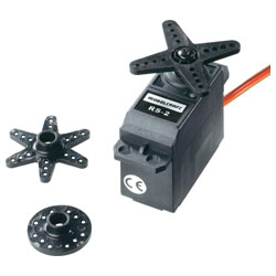 The design was made with one ting in mind, build it with modern cheap and off-the-shelf parts. I used a modelcraft RS-2 servo motor but any other standard size servomotor with the same form factor will do. I would not recommend using a micro sized servo, simply because the forces on the mechanics could be too much when moving it around by hand, and you don't want people to destroy the gear train of your servo motor by turning it too fast. A standard size servo motor is to be considered strong enough to handle this kind of abuse. The servomotor is only used for its mechanical parts, the electronics need to be removed completely. Also the potentiometer and its endstop need to be removed so that the motor can turn unrestricted.
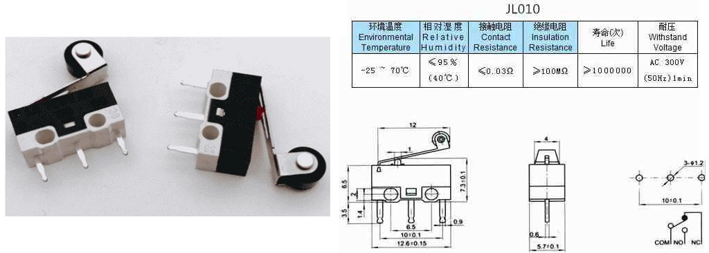
The micro-switch is perhaps the most important part of this design, and also the most crucial one if it comes to size, you can not use any other micro-switch as it would no longer fit the design for the 3D-printedparts. I used the relatively common type of micro-switche, the JL010, very compact and very cheap. I found them on aliexpress and bought them in a bag of 20 pieces for next to nothing and including shipment (what a wonderful time and age we live in). They have a relatively large activation force, which unfortunately isn't specified in the specs below, but the ones I bought, were exactly what I needed and I doubt there is much variation in force regarding this specific type. Anyway, this force is also used to make the dial plate return to it's contact position, so it is rather crucial for the performance.
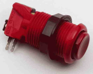 The buttons for shift and enter are regular 28 mm arcade style buttons. I had these left over from my whack-a-mole arcade cabinet and the red buttons perfectly fitted the retro computer/arcade kind of style I needed while also saving me the trouble of printing my own buttons.
For galvanic isolation, I used a relay, TF2E-5V, which most certainly isn't the best choice for this project when you look at the factors of size,simplicity and cost. But I had one of those lying around so for me it was the most obvious choice. Practically you may use any relay or optocoupler you'd like. Or leave it out completely depending on how sensitive the device you are connecting it to is, sometimes some simple resistor and set of diode connected to ground and VCC of your micro-controller circuit are more then enough to prevent against over-voltage on the input pin. However, since I didn't want to use any kind of semiconductors, I chose a relay.
Note about the driver software
In the video you see me dialing a number... then it takes some time for the number to appear on the screen. This is caused by the dial returning to its home position, which takes time, but also an extra time-out delay needs to expire before the data is accepted. This because the timeout used will allow for a huger tolerance in the time between the pulses, so that it will work as good fast fast motors as it will for slow. That is for the VIC20.For the C64 there seems to be an even bigger delay before the number is shown on screen, this is caused by the playback of the DTMF tone, the driver plays the entire tone and then puts the key value into the keyboard buffer. Now if you do not know this, it seems a little awkward and some may even doubt if the video is even real because the delay looks unnatural. However, in practice this delay is no problem at all. As it does not interfere with the user dialing, which takes also time. So the user can dial the number in a fairly normal speed. The time-out values and DTMFtone generation code code be optimized, I simply didn't took the effort, considering this entire project is just for fun and not intended to be really used. But those who want to play with the code, feel free to do so, as it is all available in the download section.
The DTMF tones are tested and really work, you could hold your land-line phone to the speaker of your TV and play the notes, then a connection will be made. Normally the DTMF tones are generated by pure sine waves,thought the SID chip cannot create sines, but a triangle is close enough to a sine wave and works just fine for this purpose.
Downloads / Github:
The VIC-20 and C64 drivers (along with the sourcecode), electrical wiring plans, mechanical 3D designs (made in FreeCAD) and the .STL file are to be found on my GitHub page: https://github.com/JanDerogee/Rotary-dial-numpadIf you decide to build your own rotary dial mechanism based on this (or parts of this) design and you decide to publish it in some form, then please do not forget to mention my name. Feel free to send me an email with a picture of what you made with it. Though the most important part should always be, that whatever you build, don't forget to have fun!