Attention: The reproducer in this article is intended for use of 2 minute cylinders (which could be wax or any other kind). The 4-minute cylinders requires a different type of stylus due to the smaller groove of the cylinder and a machine that has active tracking. Also a mechanism capable of driving it for the full duration of the max. playtime does help. If you attempt to play a 4-minute cylinder with a 2 minute stylus on a 2 minute machine, it may sound bad and the stylus may have a tendency of skating across the surface of the cylinder. This because it's relatively large diameter does not allow it to track the groove properly. However... if all goes well AND your machine is properly aligned AND positioned perfectly level then a 4 minute cylinder (which also helps if it is in perfect condition) could be very playable. The only problem then would only be that a 2 minute machine wouldn't have the power to play through the entire cylinder without rewinding somewhere around 1/2 or 2/3 of the total playtime. Believe me I tried and was slightly surprised of being able to play a 4 minute cylinder with a 0.75 mm thick glass stylus. But, although this seemed to work out for me and this situation, there are absolutely no guarantees that it will work out for everyone. In other words, this is not how this stylus is supposed to be used!
 Reproducers are effectively a membrane moved by a stylus in the form of a tiny drop of glass, which rides onto the groove on the (wax) cylinder. Because the droplet is smooth and round, it doesn't harm the delicate groove of the cylinder, but is light and strong enough to move the membrane, which in turn moves the air and therefore converting the mechanical motion into audible sound waves. Which are amplified by the horn in order to fill the entire room with sound.
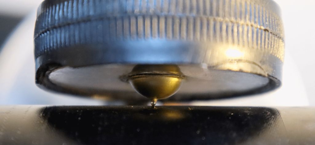
As you can see in the image above the stylus is relatively large for the grooves it needs to follow, as first you might think that this will never work, but the opposite is true. It works very nicely even if the size of the stylus in this image is slightly oversized with it's diameter of 1.0mm. This large size reduces tracking forces, but also reduces the strain on the cylinders groove. The stylus in the reproducer, as shown in the image, is a reproduction. And finding an original stylus these days could be very difficult. Because the reproducer (for a machine of this design) is completely exposed and not guarded by anything, it is therefore no surprise that these reproducers were easily damaged if the user didn't handle it carefully or more commonly, didn't store it safely when it wasn't used. And for a machine of more than a 100 years old, some maintenance and repair is always to be expected. Although in many cases, not only the stylus, but the complete reproducer was missing. Which is one of the reasons I wanted to do this project.
Now the true collector might argue that the reproducer shown on the photo's here isn't the original reproducer to begin with. And there is a truth to that, as in the beginning these machines were equipped with smaller reproducers, but were quickly replaced by these types of reproducers due to their louder sound. So Technically, what you see here is an upgrade. I have no idea when this update has taken place, it could be at the moment of sale, it could be years later. The fact is, that it is the only reproducer that I have for this machine and that there are many machines out there that have the exact same reproducer fitted. For clarity I will refer to this reproducer as "the original" on this webpage. An old advert for the reproducer I attempted to make is shown here.\
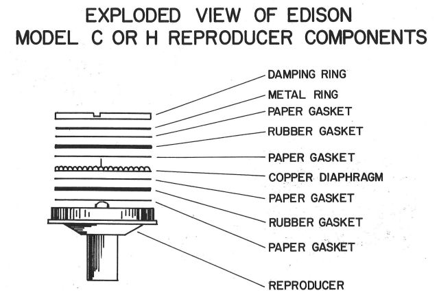 These reproducers come in many shapes and sizes but in essence they are all alike. The newest fancy models have all sorts of damping rings to reduce unwanted vibrations of the membrane and to decouple it from the case of the reproducer all in order to reproduce the best quality of sound. In practice the quality of the recordings of most (wax) cylinders is so primitive that you won't be able to hear the difference in most cases. So you won't be surprised that the simplest reproducer design just has the membrane glued directly onto the reproducer. Which is exactly what I'll do, although I'll do it using a soft type of glue in order to achieve some form of dampening. Although the dampening functionality wasn't relatively mild. Anyway, as you can see in the image below, the more fancy model of reproducer has all sorts of rings clamped together by the "damping ring", this makes it all much more complicated, so I ignore that type design and go for the Pathe version. Not only because that one is the easiest to make, but mostly because it is the proper type for that model of phonograph.
 The stylus is the blunt thingy glued onto the membrane of the reproducer, it rides the groove of the (wax) cylinder. Now these can be made of various materials, but in essence it comes down to something really hard (so it will last for a long time) and really smooth (so it doesn't damage the cylinder). But these days the most common ones are made from sapphire and glass. Where sapphire is the best choice but relatively expensive and glass is the cheaper option which you can even make yourself.
The hardness of sapphire is 9 on a scale of 10 (where 10 equals the hardness of diamond, and 1 equals the hardness of chalk). Regular household glass (soda-lime) can have a hardness of 6 but borosilicate glass has a hardness of 7.5 and is therefore the better choice if you want to make you own stylus from glass. Although you can use regular glass, it will work and it most certainly won't last very long, eventually your regular glass stylus will become flattened and sound reproduction will suffer and if you keep using it you will eventually damage your cylinders.
So if you want to make your own stylus out of glass then you really need to use borosilicate glass. Now, where do you find this type of glass? Well, the usage for this type of glass lies in it's low thermal expansion properties. Meaning that it will be able to resist heat better then regular (soda-lime) glass, because when exposed to great temperature differences, regular glass will easily crack. Borosilicate glass can withstand great heat differences and therefor can be used to make laboratory equipment (for example: beakers, test-tubes, tubes for connecting hoses, etc.) but you may also find it in your home already. Borosilicate glass is used for plates and dishes that you might put in the oven. Pyrex is a brand famous for it's heat resistant plates and dishes. They made these out of borosilicate glass for many decades in the past, unfortunately if you buy a new Pyrex plate or dish today, it no longer automatically means that you get a product made of borosilicate glass. That is because today they produce products that consist of "ordinary" tempered glass, now this certainly does have improved properties over regular glass, but it still is inferior to borosilicate glass regarding thermal expansion and hardness. But, since it is cheaper to make AND profit is important AND many customers will never even know the difference...
Anyway, some wine or other drinking glasses may be made of bororsilicate glass, simply because it is more durable and therefore can be made thinner. Although the chances that you actually own such a type of drinking glass is very small and if you do... it probably was relatively expensive so how willing would you be to smash it to pieces?
So, borosilicate glass, is the type of glass that you need. You may purchase tiny thin rods online (it can be interesting to browse through the inventory of your local chemical laboratory shop) or smash your wine cabinet and over dishes to pieces. But... don't smash them yet, first examine them to see if these items are actually made out of borosilicate glass. Because not many glass items simply aren't (since it's more expensive), but you might be lucky so it can be worth a try to find out. And even if you do know for certain which type of glass you have it still is a fun experiment. And this is a hobby project, so fun is an important part here.
The easiest way to check is by submerging it into vegetable oil, for example sunflower oil (in Dutch this is called "zonnebloem olie") has a refractive index of 1.47. Which is the same refractive index as borosilicate glass. This means that when you submerge borosilicate glass into vegetable oil, you won't get any reflections of the surface of the glass and the light that passes through it doesn't seem to bend. If you were to stick an magnifying glass made out of borosilicate glass into this fluid, it will no longer have magnifying properties, simply because the light passing through it doesn't see a difference in refraction and therefore doesn't bend. Essentially, you wouldn't even be able to see it any more. Well... if you look closely you'll still see something because nothing is perfect.
To make a long story short: when you submerge borosilicate glass into vegetable oil, it disappears (well not really, you just don't see it any more). Regular glass (soda-lime) has a slightly different refractive index and therefore does not become invisible when submerged into the oil. Below the image of a simple test with two pieces of solid glass. On the left=soda-lime glass a.ka. normal glass right=borosilicate glass, when submerged the left piece of glass is hardly visible while the right can be easily seen.
 Now if you still wonder if you did everything correct, you might want to do another test to confirm that you have indeed borosilicate glass. The heat-stress test can give you this definitive answer. Heat the glass for 60 seconds in a blue flame and then cool it down immediately by submerging it into a cup of cold water. Since regular glass is not able to handle this rapid cooling it will crackle due to the internal stress. However (because of it's much lower thermal expansion properties) borosilicate glass does not have these problem and will look completely fine. Below two images, one before the stress test and the other after. It now goes without a doubt, that the normal glass is damaged and the borosilicate glass is still fine.
 Tip: If you have trouble finding a shop that sells you very thin (1 mm or less) borosilicate glass rods then you need to go the alternative way, which might be buying borosilicate test-tubes, these are relatively cheap and are sold in laboratory equipment related (web)shops. A good shop always mentions the exact material of which the tubes are made of, this way you know that you buy the good stuff. Then when you got the tubes (which are most likely shipped in a box with much of foam and bubble wrap plastic to prevent damage during transport) put a tube in a paper/plastic bag, put on your safety gloves and glasses and gently hit the bag with a hammer. Most likely nothing will happen, so hit it again but harder, until the tube breaks, then stop hitting it, we need shards not dust. Now choose the longest, but thinnest, shard of glass and that's what you'll be using for making the stylus. Because of the high melting point of borosilicate glass, you'll need thin pieces which are easier to work with.
Regarding the size of the droplet, there is lot's of confusion. The book "the compleat talking machine" by Eric L. Reiss, mentions a drop size of 0.7 - 1.0 mm (0.027 - 0.038"), this is much larger then mentioned by the website: http://www.christerhamp.se/phono/chamouxstyl.html which mentions a size of 0.2 - 0.4 mm, which is significantly smaller! Although there seems to be a explanation for that smaller size, as the site mentions that: "Ol" phonographs had glass or sapphire styli of a diameter of 0.8 mm. But this size was meant for heavy phonograph tone arms. I have discovered that the best diameters range from 0.2 to 0.4 mm depending on the type of cylinders: engraved or molded, brand new or scratchy."
Now light or heavy are not very clear descriptions as I do not know if my reproducer will fall into the "heavy" category, but what I do know is that a smaller stylus diameter has a much easier job of following the track, simply because it's smaller diameter allows it to sink further into the groove. Therefore the larger diameter stylus is more prone to skipping or skating. But what I also know is that the smaller diameter stylus is more likely to damage the cylinder groove. This because a smaller diameter stylus concentrates the weight of the reproducer onto a smaller surface area and therefore effectively applies a greater force onto the groove of the cylinder increasing the risk of wear.
So, to keep on the safe side, I'll be rejecting anything smaller than 0,6 mm. This is also an acceptable size which you will be able to make and measure using simple tools. Do not expect your first attempt to be successful, just make a few and select the best when your done. But I can assure you, making a small stylus isn't as easy as it seems. Measuring the size of the droplet can be done with a vernier caliper but a micrometer is to be preferred. And thanks to the internet you'll be able to find a decent micrometer for less than 10 Euro (including shipment). So, I considered this all to be a nice excuse to buy me such a micrometer, which makes these kind of measurements a bit easier.
Because of the higher melting point of borosilicate glass you WILL experience problems when melting large chunks in a simple flame. The sollution is simple, either buy a better torch (gas+oxygen). For many of us a better torch isn't an option, then only way to success is to use the smallest, thinnest, piece of glass possible. You might want to experiment in order to find your limitations and work your way up from there. This way you can get a feeling about what is practical for your setup. This is very important, because it can be very frustrating when your glass just won't melt. But as long as the piece of glass is thin enough you will be able to get the job done with minimal effort using nothing but a simple torch or Bunsen burner. Patience is the key to success.
 This is how you can "convert" your stove. First remove all the unwanted items from the stove to create a clean workspace. Then remove the metal plate from the medium size burner. By removing the metal top plate, you have just disassembled the gas/air mixing chamber. So now we'll build a new mixing chamber, using four pieces from a socket wrench set (15,16,17 and 19 mm). We really need a tall mixing chamber in order to achieve a decent mixing of the gas and air. However, your stove might require a different configuration as this also depend on the size of the burners and the amount of gas it will be able to deliver. In other words, different stoves might require different sockets. Stack the sockets on top of each other, the largest at the bottom and the smallest one on top. You may now gently open up the gas and light the flame that comes out the top socket. It is important that the sockets are stacked without gaps and that they are stable! Use the stove gas regulator to change the size of the flame. Because this isn't a real Bunsen burner, you can't regulate the mixture. But honestly, you don't really need to do that because the nice people who designed the burners of the stove already designed the air intake holes already as efficient as possible, adding more holes to let more air in doesn't help.
ATTENTION: This setup may seem easy and may seem like fun, but it is not a toy! It is a serious burner and should be treated as such. Wear protective clothing and eye protection just as you would do in a lab. If you are not trained/skilled enough to operate a Bunsen burner (or stove), then you are not ready for this part of the project. Buy a decent burner or ask a skilled friend or technician for help and advise. Keep in mind that this flame is not to be compared with the normal flame coming from your stove as it is considerably larger! Always keep an appropriate safe distance during ignition and use.
Any fire, no matter it's size, is dangerous! It's always hot and has the potential to set your eyebrows, hair, clothes, house or neighborhood on fire. So when using this it's just like working with any other kind of torch, wear goggles, gloves, non combustible clothing and remember anything you've put into the fire will remain hot for a long time! Also the top socket will remain hot for a short while after use, so be careful with disassembly. Allow things to cool down.
 The source material we need can be easily obtained from your local grocery store or supermarket. They are sold as aluminum serving dishes and are a nice way to present you party snacks to your guests. They are a very cheap source of thin sheet aluminum and you can cut it with ordinary scissors. These dishes should have a thickness approximately 120 um. Checking the thickness can be done best using a micrometer.
Now a bare piece of thin flat aluminum doesn't look very attractive and isn't very rigid, so for the looks and rigidity it would be best to shape the aluminum into something with ridges. This increases the ability of the stylus to move more easily up and down while maintaining the stiffness to hold it's shape and the stylus. Shaping of the aluminum membrane also allows for a dome that holds the stylus and a decent amount of glue. This can all be integrated into the design of the membrane with no additional effort. However in order to form aluminum, some force may be required. Quite a lot of force actually if you want to do it right, since we don't want wrinkles in our membrane. So using a 3D printed mold, a thick piece of hard rubber (or many pieces of thin rubber, although a combination would be best) and a car jack this can be realized. And don't forget to add lot's of lubrication with ordinary soapy water, this allows the rubber to slide over the material instead of grabbing the material and taring/wrinkling it while pressing it against the mold.
In order to cut the perfect round shape, I used a round object of the correct size (which was a toothed belt pulley), the hole in the middle allowed the material to stay in place while cutting without permanent damage. You may also decide to use a compass however that will lead into punching a hole into the center of the circle you are about to draw/cut. Which is something that is not desirable, simply because that hole might cause the material to tare from there during the forming process, but results may vary so feel free to try.
 So I printed a mold with the shape I wanted, smoothed and polished it as much as I could and allowed it for a long time to "dry" and "harden", because I printed in ABS I could smooth it using acetone. But acetone makes it soft meaning that you can't use it as a mold. So letting it "dry" for a fey days makes the acetone evaporate completely from the ABS plastic and it's original strength is restored. Now a proper mold consists of 2 halves and I only halve one halve. This is because a perfect mold that has to perfectly fitting parts is difficult to make right, so I decided to go for a halve mold and some rubber as the counterpart of the mold. The idea is that the rubber, under heavy pressure, will force the aluminum into the shape of the mold. Now in order to do so, you'll need some considerable force, but a decent construction and a small hydraulic car jack, can do the job. Unfortunately, making a decent construction to withstand all these forces is something where I encountered great problems. Fortunately I could manage by using some lashing strap to keep it all in place. Normally these kind of constructions are made out of metal welded together, now would did work for the first of many attempts I did in experimenting, but every time the construction failed a little bit more, to the point where it no longer could withstand the forces of the car jack at all. No matter how many screws I used and glue I tried to pour in. But the lashing straps were a life saver and allowed me to continue experimenting until I finally reached my goal of the perfect membrane. Because although the information on this website make it look like an easy job, in essence it took me lot's of tries to get everything right and to develop some experience and feel for the processes involved.
 Now when applying pressure the idea is that the metal will deform, it will compress at some places and stretch at other places. But the amount of compressing and stretching is limited. So it is not possible to make a complex shape in one press. Fortunately, this shape isn't to complex. The dome will be made manually, with a rotating ball and decent lubrication. Lubrication is important, soap is a great lubricant for this application. A drop of oil will also do the trick but is a bit more difficult to remove and considering that we need to apply glue during the final stages of assembly. Therefore it is better not to use oil. Lubricant is used in all stages of shaping the aluminum. In order to make the dome a drill-press is used, with something that is essentially a ball on a stick the final shape of the dome is formed, the movement of the ball combined with the movement of the aluminum allows the shape to be gently formed. If this was done using the jack, the dome would rupture due to the stress. Using the rotating drill press some fluidity of the aluminum is realized and more stretching of the aluminum is allowed.
Now in the video I made, I used regular glass instead of borosillicate glass, this because in the video I could no properly film the sequency of extracting the glass, it simply took too long and it all looked too clumsy. So, to make things more practical to film and to explain, regular glass was used. Still not easy to film though, but easier. Anyway, with this regular glass stylus I played around for approximately 45 minutes of continuous playtime, checking the stylus for wear and damage but I did not see any of it. I even checked with a microscope and it all looked just as fine as when I began. No flattened side at all. Why would that be? Well there are reason to believe that it has to do with the reduced weight of the reproducer, as the 3D printed one is much lighter than the original one. The 3D printed reproducer applies a force onto the stylus of 0.044kg*9.8m/s2 = 0.43N, compared to the original of 0.077kg*9.8m/s2=0.75N. So less force results in less wear of the stylus (and the cylinder). Now don't get me wrong here, the use of borosillicate glass is still the preferred type of glass, but regular glass isn't as bad as I expected. So that was a nice surprise. Now I wonder how it would look like after 100 hours of continuous playtime, something I'll never know I guess, because I do not have that many cylinders so this experiment would get boring quite quickly. But seriously, borosilicate glass is the only proper type of glass you should use if you decide to make a stylus in order to restore your machine.
 Regarding loudness, both the old and the new reproducer are very loud, no issues there. One thing is certain, it works, but further refinement is required in order to achieve the exact same behavior as the original reproducer. But it was a fun experiment that has lot's of potential in being an acceptable replacement part.
But as technology progressed, cylinders were also made of more modern materials, the quality of these recordings was much better and they were much much more durable in many ways. In fact they were so much more durable that they were marketed as "indestructible". Now although they were revolutionary in many ways, indestructible is relative term, what they really meant that if you use them normally the seem to last forever. You still should handle them with respect and care. For more info about the history of cylinders visit: https://psap.library.illinois.edu/collection-id-guide/cylinder
Knowing the above, it is important to know the difference and how to recognize them. Because if you attempt to playback a 2 minute cylinder on a 4 minute machine and vice versa, it would not sound well and damage is not unlikely to occur.
The 4 minute cylinders have a much finer track, so if you have good eyes (or a good magnifier) you might be able to see the difference. But there are easier clues, because in practice every 4 minute cylinder (Except Edison Blue Amberols) will have "4M" before the record number on the edge of the cylinder. For example: if the record number is 1234 it's a 2 min record, but if the number is 4M-1234 then it's a 4 minute record.
For the Edison Blue Amberol's, the opposite is true, for example: a Blue Amberol marked 1234 is a 4 minute record, but a 2 minute version is marked with an additional 2M before the number, so these will read 2M-1234. Now this can all be very confusing if you have just one single cylinder and nothing to compare it with. I can assure you, when you have both versions and are able to compare them side by side things will become much more obvious.
Why this project?
Well, mostly for the fun of it. I decided to build a reproducer, to experience how hard it would be to recreate a essential part of something that was high-tech more than a 100 years ago. These days, you don't need fancy equipment, clock makers patience or precision to get something usable (and safe for your cylinders). And if you happen to own a 3D printer you can go straight into the interesting part. Which is melting glass into a well defined but tiny droplet for the stylus and forming aluminum into an interesting shape for the membrane. I really enjoyed the first time I used it and the sound it produced was magical. And all without any electronic circuit.
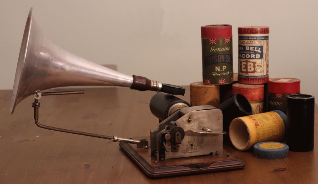
What is a reproducer?
A reproducer is the part that is placed between the horn and the (wax) cylinder that contains the music. It converts the humps and bumps of the (wax) cylinder into audible waves that are amplified by the horn of the phonograph. You can see one in the image below where it's stylus is resting onto the groove of the cylinder.
Reproducers are effectively a membrane moved by a stylus in the form of a tiny drop of glass, which rides onto the groove on the (wax) cylinder. Because the droplet is smooth and round, it doesn't harm the delicate groove of the cylinder, but is light and strong enough to move the membrane, which in turn moves the air and therefore converting the mechanical motion into audible sound waves. Which are amplified by the horn in order to fill the entire room with sound.
As you can see in the image above the stylus is relatively large for the grooves it needs to follow, as first you might think that this will never work, but the opposite is true. It works very nicely even if the size of the stylus in this image is slightly oversized with it's diameter of 1.0mm. This large size reduces tracking forces, but also reduces the strain on the cylinders groove. The stylus in the reproducer, as shown in the image, is a reproduction. And finding an original stylus these days could be very difficult. Because the reproducer (for a machine of this design) is completely exposed and not guarded by anything, it is therefore no surprise that these reproducers were easily damaged if the user didn't handle it carefully or more commonly, didn't store it safely when it wasn't used. And for a machine of more than a 100 years old, some maintenance and repair is always to be expected. Although in many cases, not only the stylus, but the complete reproducer was missing. Which is one of the reasons I wanted to do this project.
Now the true collector might argue that the reproducer shown on the photo's here isn't the original reproducer to begin with. And there is a truth to that, as in the beginning these machines were equipped with smaller reproducers, but were quickly replaced by these types of reproducers due to their louder sound. So Technically, what you see here is an upgrade. I have no idea when this update has taken place, it could be at the moment of sale, it could be years later. The fact is, that it is the only reproducer that I have for this machine and that there are many machines out there that have the exact same reproducer fitted. For clarity I will refer to this reproducer as "the original" on this webpage. An old advert for the reproducer I attempted to make is shown here.\
These reproducers come in many shapes and sizes but in essence they are all alike. The newest fancy models have all sorts of damping rings to reduce unwanted vibrations of the membrane and to decouple it from the case of the reproducer all in order to reproduce the best quality of sound. In practice the quality of the recordings of most (wax) cylinders is so primitive that you won't be able to hear the difference in most cases. So you won't be surprised that the simplest reproducer design just has the membrane glued directly onto the reproducer. Which is exactly what I'll do, although I'll do it using a soft type of glue in order to achieve some form of dampening. Although the dampening functionality wasn't relatively mild. Anyway, as you can see in the image below, the more fancy model of reproducer has all sorts of rings clamped together by the "damping ring", this makes it all much more complicated, so I ignore that type design and go for the Pathe version. Not only because that one is the easiest to make, but mostly because it is the proper type for that model of phonograph.
Making a "stylus" from what?
The stylus is the blunt thingy glued onto the membrane of the reproducer, it rides the groove of the (wax) cylinder. Now these can be made of various materials, but in essence it comes down to something really hard (so it will last for a long time) and really smooth (so it doesn't damage the cylinder). But these days the most common ones are made from sapphire and glass. Where sapphire is the best choice but relatively expensive and glass is the cheaper option which you can even make yourself.
The hardness of sapphire is 9 on a scale of 10 (where 10 equals the hardness of diamond, and 1 equals the hardness of chalk). Regular household glass (soda-lime) can have a hardness of 6 but borosilicate glass has a hardness of 7.5 and is therefore the better choice if you want to make you own stylus from glass. Although you can use regular glass, it will work and it most certainly won't last very long, eventually your regular glass stylus will become flattened and sound reproduction will suffer and if you keep using it you will eventually damage your cylinders.
So if you want to make your own stylus out of glass then you really need to use borosilicate glass. Now, where do you find this type of glass? Well, the usage for this type of glass lies in it's low thermal expansion properties. Meaning that it will be able to resist heat better then regular (soda-lime) glass, because when exposed to great temperature differences, regular glass will easily crack. Borosilicate glass can withstand great heat differences and therefor can be used to make laboratory equipment (for example: beakers, test-tubes, tubes for connecting hoses, etc.) but you may also find it in your home already. Borosilicate glass is used for plates and dishes that you might put in the oven. Pyrex is a brand famous for it's heat resistant plates and dishes. They made these out of borosilicate glass for many decades in the past, unfortunately if you buy a new Pyrex plate or dish today, it no longer automatically means that you get a product made of borosilicate glass. That is because today they produce products that consist of "ordinary" tempered glass, now this certainly does have improved properties over regular glass, but it still is inferior to borosilicate glass regarding thermal expansion and hardness. But, since it is cheaper to make AND profit is important AND many customers will never even know the difference...
Anyway, some wine or other drinking glasses may be made of bororsilicate glass, simply because it is more durable and therefore can be made thinner. Although the chances that you actually own such a type of drinking glass is very small and if you do... it probably was relatively expensive so how willing would you be to smash it to pieces?
So, borosilicate glass, is the type of glass that you need. You may purchase tiny thin rods online (it can be interesting to browse through the inventory of your local chemical laboratory shop) or smash your wine cabinet and over dishes to pieces. But... don't smash them yet, first examine them to see if these items are actually made out of borosilicate glass. Because not many glass items simply aren't (since it's more expensive), but you might be lucky so it can be worth a try to find out. And even if you do know for certain which type of glass you have it still is a fun experiment. And this is a hobby project, so fun is an important part here.
The easiest way to check is by submerging it into vegetable oil, for example sunflower oil (in Dutch this is called "zonnebloem olie") has a refractive index of 1.47. Which is the same refractive index as borosilicate glass. This means that when you submerge borosilicate glass into vegetable oil, you won't get any reflections of the surface of the glass and the light that passes through it doesn't seem to bend. If you were to stick an magnifying glass made out of borosilicate glass into this fluid, it will no longer have magnifying properties, simply because the light passing through it doesn't see a difference in refraction and therefore doesn't bend. Essentially, you wouldn't even be able to see it any more. Well... if you look closely you'll still see something because nothing is perfect.
To make a long story short: when you submerge borosilicate glass into vegetable oil, it disappears (well not really, you just don't see it any more). Regular glass (soda-lime) has a slightly different refractive index and therefore does not become invisible when submerged into the oil. Below the image of a simple test with two pieces of solid glass. On the left=soda-lime glass a.ka. normal glass right=borosilicate glass, when submerged the left piece of glass is hardly visible while the right can be easily seen.
Now if you still wonder if you did everything correct, you might want to do another test to confirm that you have indeed borosilicate glass. The heat-stress test can give you this definitive answer. Heat the glass for 60 seconds in a blue flame and then cool it down immediately by submerging it into a cup of cold water. Since regular glass is not able to handle this rapid cooling it will crackle due to the internal stress. However (because of it's much lower thermal expansion properties) borosilicate glass does not have these problem and will look completely fine. Below two images, one before the stress test and the other after. It now goes without a doubt, that the normal glass is damaged and the borosilicate glass is still fine.
Tip: If you have trouble finding a shop that sells you very thin (1 mm or less) borosilicate glass rods then you need to go the alternative way, which might be buying borosilicate test-tubes, these are relatively cheap and are sold in laboratory equipment related (web)shops. A good shop always mentions the exact material of which the tubes are made of, this way you know that you buy the good stuff. Then when you got the tubes (which are most likely shipped in a box with much of foam and bubble wrap plastic to prevent damage during transport) put a tube in a paper/plastic bag, put on your safety gloves and glasses and gently hit the bag with a hammer. Most likely nothing will happen, so hit it again but harder, until the tube breaks, then stop hitting it, we need shards not dust. Now choose the longest, but thinnest, shard of glass and that's what you'll be using for making the stylus. Because of the high melting point of borosilicate glass, you'll need thin pieces which are easier to work with.
Making a "stylus" from a drop of glass
Now that you know which glass to use and how to recognize it, you can start to form it into the stylus shape required. In other words, what we'll need is a tiny stick of glass of which one end will have a perfectly rounded (droplet) shape.Regarding the size of the droplet, there is lot's of confusion. The book "the compleat talking machine" by Eric L. Reiss, mentions a drop size of 0.7 - 1.0 mm (0.027 - 0.038"), this is much larger then mentioned by the website: http://www.christerhamp.se/phono/chamouxstyl.html which mentions a size of 0.2 - 0.4 mm, which is significantly smaller! Although there seems to be a explanation for that smaller size, as the site mentions that: "Ol" phonographs had glass or sapphire styli of a diameter of 0.8 mm. But this size was meant for heavy phonograph tone arms. I have discovered that the best diameters range from 0.2 to 0.4 mm depending on the type of cylinders: engraved or molded, brand new or scratchy."
Now light or heavy are not very clear descriptions as I do not know if my reproducer will fall into the "heavy" category, but what I do know is that a smaller stylus diameter has a much easier job of following the track, simply because it's smaller diameter allows it to sink further into the groove. Therefore the larger diameter stylus is more prone to skipping or skating. But what I also know is that the smaller diameter stylus is more likely to damage the cylinder groove. This because a smaller diameter stylus concentrates the weight of the reproducer onto a smaller surface area and therefore effectively applies a greater force onto the groove of the cylinder increasing the risk of wear.
So, to keep on the safe side, I'll be rejecting anything smaller than 0,6 mm. This is also an acceptable size which you will be able to make and measure using simple tools. Do not expect your first attempt to be successful, just make a few and select the best when your done. But I can assure you, making a small stylus isn't as easy as it seems. Measuring the size of the droplet can be done with a vernier caliper but a micrometer is to be preferred. And thanks to the internet you'll be able to find a decent micrometer for less than 10 Euro (including shipment). So, I considered this all to be a nice excuse to buy me such a micrometer, which makes these kind of measurements a bit easier.
Because of the higher melting point of borosilicate glass you WILL experience problems when melting large chunks in a simple flame. The sollution is simple, either buy a better torch (gas+oxygen). For many of us a better torch isn't an option, then only way to success is to use the smallest, thinnest, piece of glass possible. You might want to experiment in order to find your limitations and work your way up from there. This way you can get a feeling about what is practical for your setup. This is very important, because it can be very frustrating when your glass just won't melt. But as long as the piece of glass is thin enough you will be able to get the job done with minimal effort using nothing but a simple torch or Bunsen burner. Patience is the key to success.
Converting the kitchen stove into a Bunsen burner
If you don't have a blowtorch but do have a kitchen stove that works on gas then you might consider making an improvised Bunsen burner. Technically a stove isn't all that different. In both cases the gas flows into a mixing chamber and where the mixed gas exits, it will burn. So basically the stove already is a sort of Bunsen burner one but with multiple flames and a much flatter mixing chamber, the major difference is that the stove has no way to regulate the air intake. Which is a good thing for a stove. But the major drawback of a stove (for our purpose) is the shape of the flame, all those tiny flames are useless if you want to hold something large directly into these flames. The trick below essentially combines all those tiny flames into a single much more usable flame... useful for our experiment that is.
This is how you can "convert" your stove. First remove all the unwanted items from the stove to create a clean workspace. Then remove the metal plate from the medium size burner. By removing the metal top plate, you have just disassembled the gas/air mixing chamber. So now we'll build a new mixing chamber, using four pieces from a socket wrench set (15,16,17 and 19 mm). We really need a tall mixing chamber in order to achieve a decent mixing of the gas and air. However, your stove might require a different configuration as this also depend on the size of the burners and the amount of gas it will be able to deliver. In other words, different stoves might require different sockets. Stack the sockets on top of each other, the largest at the bottom and the smallest one on top. You may now gently open up the gas and light the flame that comes out the top socket. It is important that the sockets are stacked without gaps and that they are stable! Use the stove gas regulator to change the size of the flame. Because this isn't a real Bunsen burner, you can't regulate the mixture. But honestly, you don't really need to do that because the nice people who designed the burners of the stove already designed the air intake holes already as efficient as possible, adding more holes to let more air in doesn't help.
ATTENTION: This setup may seem easy and may seem like fun, but it is not a toy! It is a serious burner and should be treated as such. Wear protective clothing and eye protection just as you would do in a lab. If you are not trained/skilled enough to operate a Bunsen burner (or stove), then you are not ready for this part of the project. Buy a decent burner or ask a skilled friend or technician for help and advise. Keep in mind that this flame is not to be compared with the normal flame coming from your stove as it is considerably larger! Always keep an appropriate safe distance during ignition and use.
Any fire, no matter it's size, is dangerous! It's always hot and has the potential to set your eyebrows, hair, clothes, house or neighborhood on fire. So when using this it's just like working with any other kind of torch, wear goggles, gloves, non combustible clothing and remember anything you've put into the fire will remain hot for a long time! Also the top socket will remain hot for a short while after use, so be careful with disassembly. Allow things to cool down.
The casing of the reproducer
Well... fire up the 3D printer and print as many as you like. If you print in ABS you will be able to smooth it afterwards using acetone, which will result in a much nicer end result. Also ABS is less likely to warp if you leave it in your car in a sunny day. Although that would be a very bad thing for your cylinders too.The membrane
In many reproducers of this type mica was used as a membrane. Now although mica was a very common material once, it isn't as easy to obtain as it used to be and it can be very expensive. But in the past they also made membranes from metal, sometimes even glass! But the most practical and cheapest option we have today is perhaps aluminum. Now aluminum may not have been the choice for a membrane in the past, it will do fine today. After all, there is no reason to be picky, considering we use ABS plastic for printing the casing of the reproducer, that material wasn't used either. Keep in mind that this whole project is a hobby project, intended to be fun functional and does not really focus on historical accuracy.
The source material we need can be easily obtained from your local grocery store or supermarket. They are sold as aluminum serving dishes and are a nice way to present you party snacks to your guests. They are a very cheap source of thin sheet aluminum and you can cut it with ordinary scissors. These dishes should have a thickness approximately 120 um. Checking the thickness can be done best using a micrometer.
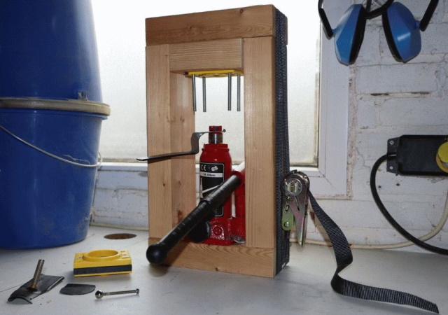
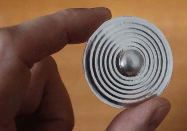
Now a bare piece of thin flat aluminum doesn't look very attractive and isn't very rigid, so for the looks and rigidity it would be best to shape the aluminum into something with ridges. This increases the ability of the stylus to move more easily up and down while maintaining the stiffness to hold it's shape and the stylus. Shaping of the aluminum membrane also allows for a dome that holds the stylus and a decent amount of glue. This can all be integrated into the design of the membrane with no additional effort. However in order to form aluminum, some force may be required. Quite a lot of force actually if you want to do it right, since we don't want wrinkles in our membrane. So using a 3D printed mold, a thick piece of hard rubber (or many pieces of thin rubber, although a combination would be best) and a car jack this can be realized. And don't forget to add lot's of lubrication with ordinary soapy water, this allows the rubber to slide over the material instead of grabbing the material and taring/wrinkling it while pressing it against the mold.
In order to cut the perfect round shape, I used a round object of the correct size (which was a toothed belt pulley), the hole in the middle allowed the material to stay in place while cutting without permanent damage. You may also decide to use a compass however that will lead into punching a hole into the center of the circle you are about to draw/cut. Which is something that is not desirable, simply because that hole might cause the material to tare from there during the forming process, but results may vary so feel free to try.
Forcing metal into shape
Well... this sounds like something that does require a lot of force which indeed is the case. Even a thin slice of aluminum like this does require some force to get it correctly in the proper shape. Although you could trade "force" for "time". Because, if you are very skilled, you might emboss the desired pattern into the metal disc. But beware, when you are done chances are that it won't look as flat as you'd like. So, lacking some decent embossing skills I decided to go for the "force" method.
So I printed a mold with the shape I wanted, smoothed and polished it as much as I could and allowed it for a long time to "dry" and "harden", because I printed in ABS I could smooth it using acetone. But acetone makes it soft meaning that you can't use it as a mold. So letting it "dry" for a fey days makes the acetone evaporate completely from the ABS plastic and it's original strength is restored. Now a proper mold consists of 2 halves and I only halve one halve. This is because a perfect mold that has to perfectly fitting parts is difficult to make right, so I decided to go for a halve mold and some rubber as the counterpart of the mold. The idea is that the rubber, under heavy pressure, will force the aluminum into the shape of the mold. Now in order to do so, you'll need some considerable force, but a decent construction and a small hydraulic car jack, can do the job. Unfortunately, making a decent construction to withstand all these forces is something where I encountered great problems. Fortunately I could manage by using some lashing strap to keep it all in place. Normally these kind of constructions are made out of metal welded together, now would did work for the first of many attempts I did in experimenting, but every time the construction failed a little bit more, to the point where it no longer could withstand the forces of the car jack at all. No matter how many screws I used and glue I tried to pour in. But the lashing straps were a life saver and allowed me to continue experimenting until I finally reached my goal of the perfect membrane. Because although the information on this website make it look like an easy job, in essence it took me lot's of tries to get everything right and to develop some experience and feel for the processes involved.
Now when applying pressure the idea is that the metal will deform, it will compress at some places and stretch at other places. But the amount of compressing and stretching is limited. So it is not possible to make a complex shape in one press. Fortunately, this shape isn't to complex. The dome will be made manually, with a rotating ball and decent lubrication. Lubrication is important, soap is a great lubricant for this application. A drop of oil will also do the trick but is a bit more difficult to remove and considering that we need to apply glue during the final stages of assembly. Therefore it is better not to use oil. Lubricant is used in all stages of shaping the aluminum. In order to make the dome a drill-press is used, with something that is essentially a ball on a stick the final shape of the dome is formed, the movement of the ball combined with the movement of the aluminum allows the shape to be gently formed. If this was done using the jack, the dome would rupture due to the stress. Using the rotating drill press some fluidity of the aluminum is realized and more stretching of the aluminum is allowed.
Assembly of the reproducer
Now that we have all the parts we need (3D printed reproducer case, glass stylus and aluminum membrane), we can assemble the transducer. We need to glue the stylus to the membrane (in the past they used a hard type of bee wax but but the modern person of the 21st century simply uses two component epoxy glue). Allow the glue at least 24 hours to dry after placement of the stylus. Even if the box says that it is 5 minute epoxy, allow it to cure properly for 24 hours to reach it's full strength. Only after the glue has fully hardened you may trim the excessive part of the stylus carefully. And in order to glue the membrane to the reproducer, we need to use some type of glue that remains relatively soft when fully dried, this way we mimic the rubber gaskets normally used in the more expensive/advanced reproducers. Although I doubt if people will ever hear the difference if you decide to glue it on using epoxy glue. Because, honestly, this isn't a hifi system. But, a liberal amount of hobby glue to attach the membrane will do just fine. Now don't get me wrong, adding some decent dampers/gaskets would be better but it would also make it slightly more complicated.Conclusion
Well... the 3D printed reproducer with a glass stylus and aluminum membrane does work. It works rather well actually. Although there are some issues. For instance the weight of the 3D printed reproducer is considerably lower then the original one, which is not a problem, actually, it might be even better for the cylinder. But sound leaks out of the 3D printed reproducer much more then it does on the original one. This is most likely caused by the fact that the 3D printed reproducer doesn't have enough mass and the reproducer acts like a soundbox in a slightly different manor than the original (heavier) version. Most likely more damping is required between the membrane and the soundbox, this way the vibrations of the membrane aren't directly transferred to the reproducer. Perhaps I chosen the wrong glue or perhaps I should have cut the membrane slighly smaller so it couldn't touch the reproducer via the sides of the membrane. But to be honest, this isn't a really big deal.Now in the video I made, I used regular glass instead of borosillicate glass, this because in the video I could no properly film the sequency of extracting the glass, it simply took too long and it all looked too clumsy. So, to make things more practical to film and to explain, regular glass was used. Still not easy to film though, but easier. Anyway, with this regular glass stylus I played around for approximately 45 minutes of continuous playtime, checking the stylus for wear and damage but I did not see any of it. I even checked with a microscope and it all looked just as fine as when I began. No flattened side at all. Why would that be? Well there are reason to believe that it has to do with the reduced weight of the reproducer, as the 3D printed one is much lighter than the original one. The 3D printed reproducer applies a force onto the stylus of 0.044kg*9.8m/s2 = 0.43N, compared to the original of 0.077kg*9.8m/s2=0.75N. So less force results in less wear of the stylus (and the cylinder). Now don't get me wrong here, the use of borosillicate glass is still the preferred type of glass, but regular glass isn't as bad as I expected. So that was a nice surprise. Now I wonder how it would look like after 100 hours of continuous playtime, something I'll never know I guess, because I do not have that many cylinders so this experiment would get boring quite quickly. But seriously, borosilicate glass is the only proper type of glass you should use if you decide to make a stylus in order to restore your machine.
Regarding loudness, both the old and the new reproducer are very loud, no issues there. One thing is certain, it works, but further refinement is required in order to achieve the exact same behavior as the original reproducer. But it was a fun experiment that has lot's of potential in being an acceptable replacement part.
Technical details about (wax) cylinders
The phonograph plays music stored on a media that is shaped in the form of a cylinder. This cylinder was originally made from wax, the earliest ones were a light brown color and the later ones black for more info how to handle these, visit: https://www.cylinder.de/guide_black-wax-cylinders.htmlBut as technology progressed, cylinders were also made of more modern materials, the quality of these recordings was much better and they were much much more durable in many ways. In fact they were so much more durable that they were marketed as "indestructible". Now although they were revolutionary in many ways, indestructible is relative term, what they really meant that if you use them normally the seem to last forever. You still should handle them with respect and care. For more info about the history of cylinders visit: https://psap.library.illinois.edu/collection-id-guide/cylinder
Special formats
As with every format... there are variations for more info visit: https://blog.discogs.com/en/cylinders-more-than-a-series-of-tubesRegular format: 2 minute vs 4 minute
Technically you would require a different stylus to play a 4 minute cylinder than you would to play a 2 minute cylinder. In practice there is a bit more nuance to this claim, but in essence it is true. Simply because the grooves are closer together and smaller a large stylus able to play a 2 minute cylinder properly might struggle with a 4 minute one. But a stylus at the smallest possible size able to play a 2 minute cylinder might just as well play a 4 minute one without problems. But, for the preservation of your cylinders, just play the things like they were intended, on the proper machine with the proper stylus.Knowing the above, it is important to know the difference and how to recognize them. Because if you attempt to playback a 2 minute cylinder on a 4 minute machine and vice versa, it would not sound well and damage is not unlikely to occur.
The 4 minute cylinders have a much finer track, so if you have good eyes (or a good magnifier) you might be able to see the difference. But there are easier clues, because in practice every 4 minute cylinder (Except Edison Blue Amberols) will have "4M" before the record number on the edge of the cylinder. For example: if the record number is 1234 it's a 2 min record, but if the number is 4M-1234 then it's a 4 minute record.
For the Edison Blue Amberol's, the opposite is true, for example: a Blue Amberol marked 1234 is a 4 minute record, but a 2 minute version is marked with an additional 2M before the number, so these will read 2M-1234. Now this can all be very confusing if you have just one single cylinder and nothing to compare it with. I can assure you, when you have both versions and are able to compare them side by side things will become much more obvious.