This page shows the improved version of lighthammer. This version uses a better hit-detection-mechanism and has a 3D printed body, instead of a modified plastic toy used in the first prototype. The lighthammer is a lightpen-type device for use with a CRT monitor. With this device games using the lightpen/lightgun technology get a slightly different twist. Allowing for more interaction between the game, the screen and the player. Unfortunately, it's only 30 years too late.
What is it:
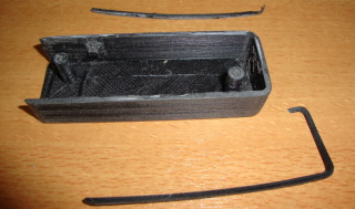
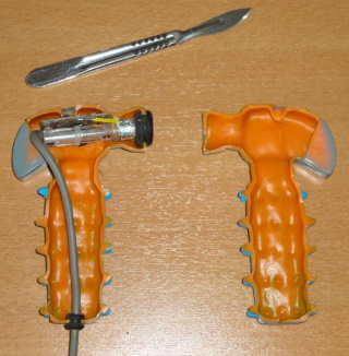 Soon after release of the lighthammer (v1.0) project it became clear that the design was far from perfect. It simply did not operate as expected. Although position sensing was great, the hit detection was unreliable. Sometimes too sensitive, sometimes not sensitive at all. And some of the time the sensor didn't fully return to it's default position so an additional hit on the lighthammer itself was required to continue playing. So I dissected the lighthammer, by cutting it into two parts. This looked nice for a photo and ensured that I could never go back. Therefore the only sollution was to build a new (and better) lighthammer. So, back to the drawing board for the next version of the lighthammer, version 2.0.
The new design should be something for everyone to build, where the original design relied on a small toy (a toy for dogs, to chew on). The new design should not rely on existing toys at all, but on easy available parts. This way everyone who wants to (or someone they know) can make the lighthammer themselves. Only this way the lighthammer could grow into a input device that will be used all over the world... whahahahahaha (evil laughter, sorry, I could not resist). Anyway, the new design should make everything much easier and it most certainly should be able to fit all the electronics inside the hammer easily.
The old hit detection sensor was a small tube with a piece of iron and a spring, this created a simple switch, but electrically the switching action was noisy and switching times were too short to be detected properly therefore some electronics were required to get the signals into proper shape for the C64 computer to process it.
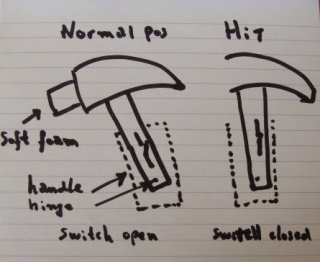 The new design is just a plain micro switch. A switch you can find everywhere on ebay because it is still widely used in arcade-style buttons. But the beauty is not in the switch but in the way the switch is activated. By turning the handle of the hammer into one part of a hinge and the hammer itself the other part of the hinge, the switch can detect the "bending" of the hammer, which will take place when the hammer head hit's the screen. Easy and in style. These new design features result in a setup that is electrically identical to the Magnum Light Phazer lightgun, so this means that you can use the lighthammer to play games like "operation wolf", sure the game play would be really silly, but it is still a funny bonus to the design.
The switch most certainly gives the hammer the familiar arcade style "clicking" sound, this also indicates when the switching action takes place. This is, with a fancy word, called "user feedback". This kind of feedback confirms the user that it all works and therefore makes it much more fun to use. Most people don't realize that such a simple click could be so important. However, there's only one small problem, the WAF (wife acceptance factor). My wife does not always appreciate the game sounds and clicking noises of joysticks and lighthammers. But then again I should not have placed the arcade cabinet in the living room and expected everything to be fine when I loudly play it while her favorite television soap is on TV.
The new design
The new design is fully 3D printed, and in order to get the perfect design (okay, perhaps not perfect, but certainly good enough) many prototypes have been tried out and tested, the design that made it consists of four 3D printed parts. The hammer head, the rod connecting it to the handle, the handle itself and the lid for the handle. All parts were designed in FreeCAD, now there are many things you can say about FreeCAD and it has it's problems if your design isn't right the first time, but FreeCAD will certainly get the job done and as the name states... it is completely free. For everyone who likes to play with FreeCAD lighthammer designs, the design files can be found in the downloads section at the bottom of this page.Making the parts
 All the parts (head, rod, handle and handle cover) of the hammer can be 3D printed. The 3D printed parts can be printed in any kind of plastic the user may like and the colors used are just a matter of taste. But I would like to suggest that it is best to print it in ABS (that's what I did), this because with ABS it can be modified much easier afterwards. On the left you see my 3D printer, it just a simple contraption of wood, MDF and old printer parts combined with an cheap all metal Chinese 3mm extruder from ebay. The whole contraption is controlled by Mach3 and splic3r. I was already familiar with Mach3 because of my CNC machine, so when I build the 3D printer that was a logical step and it turned out to work great.
Important for ABS printing is a heated bed, keep the temperature constant and at such a level that the print stays on the board until you are done. Sometimes it won't pop off completely and then you have warping. The only way I could accomplish this (because my printer is placed directly at the floor underneath my desk) is by building a small chamber/tent (from bed sheets), to prevent a draft (wind) to cool down my part. Expensive printers have solved this by having their own chamber directly around the printing area. I set my heated bed to a temperature of 100 deg Celsius. and I also use a small layer of hairspray to keep the part stick to the bed. Which also makes the room smell a little less like plastic and a lot like a barbershop, which is a good thing considering I'm not the only one in this house and the smell of barbershops seems to be preferred above plastic. This is a big pulse for the WAF of any 3D printer (WAF stands for: Wife Acceptance Factor). So in short, you do not need anything fancy or expensive. The required files for 3D printing are to be found in the downloads section at the bottom of this page. I printed all the parts with a fill ratio of 20% (sliced using "Slic3r"), but perhaps it would have been better to make the handle and rod with a fill ratio, perhaps 100%. Important is that the hammerhead itself should be printed at the lowest possible density, simply to keep the weight down, because you're hitting thigs with it you do not want to be damaged.
Smoothing the parts
 The components (if printed in ABS) can be treated with acetone to make them look much smoother.
SAFETY NOTE: Only do this outside and keep in mind that acetone vapor is highly flammable! Therefore no smoking or open fire is allowed during this procedure! You may only do this using a heat resistant yar, we do no want the glass to crack due to the stresses caused by sudden increase of temperature.
First some sanding is required to make it smooth, then the whole is placed into a jar filled with a small amount of acetone (exactly the amount you need to create a decent vapor once the jar will be heated). The part itself must not come into direct contact with the acetone. The smoothing is done using acetone vapor. So in the example picture to the left you see a special rig I made to hold the item in place during the smoothing procedure. During this procedure the part will become much softer and it will attach itself to the rig, so the point where the part touches the rig must be out of view when finished. Also make sure that that parts is strong enough to hold it in place, and properly balanced. Otherwise the part might deform of falls off when the plastic softens.
To create the vapor we must heat the acetone to approx 50 degrees Celsius. The easiest (and perhaps safest way) to do this is by placing the jar into a small bucket then fill the bucket with water that has the desired temperature (I used boiling water because the water cools down pretty quickly due to the mass of the jar). We can't use too much water because that will make the jar float in the bucket and perhaps tip over.
Now there is one thing to consider, condensation. The jar is cold on the top, so the vapor will condensate on the top of the jar, this will cause droplets of acetone. Now these droplets WILL eventually fall back down, you do not want it to fall on your part. How to solve this, well you can tilt the jar a little bit (by placing a coin under one side of the jar), then the droplets will go to the lowest point of the top of the jar and from there they will fall down. Which is most likely near the edge of the jar.
From the moment the vapor will begin to rise, it will condense onto the part, this is only a small amount of acetone, the parts quickly heats up by the vapor. And soon the condensation stops. At this point there is enough acetone to do the smoothing but not enough to damage the part, that is if you do not leave the part in the jar for too long. How long the part should be in the vapor is a matter of the size of the part, the size of the jar, the desired result, etc. So in short, you need to monitor the part and confirm if it still looks OK. Then when you think it is almost smooth enough, you open the lid of the jar and let the vapor escape. Note the word "almost", because the smoothing continues after removal from the jar, simply because there is still acetone on the part and absorbed by the part. Also, remove the jar from the bucket and let it all cool down. The part itself is soft and when you touch it you will leave marks and fingerprints, so prevent touching the part in visible areas. When the part is removed from the jar you must let it "dry" or "harden" for at least 24 hours, preferably on a flat area, but keep in mind that the part might stick onto the surface you place it on, so only remove when the part has regained it's original strength. Again it is best to place the part on a side that is the least important to look at. Repeat the entire process if you are not satisfied with the results.
Secure the small screw posts
 Before I did anything with the handle I secured the small screw posts by adding an extra screw to each post. Although the design appears to be meant for only 2 screws (which are placed only on the side of the handle cover) it is a very good idea to also add an extra screw on the other side of the handle too. This because these small posts would otherwise break off too easy which is prevented by the extra screw. In order to do so I drilled a small hole from the inside of the handle to the outside and then countersunk the hole. The drilling of the hole is also required because most 3D printers will print the hole too small making it unusable, by drilling it with a 2mm drill it will be perfect for any small self tapping screw.
The handle and rod
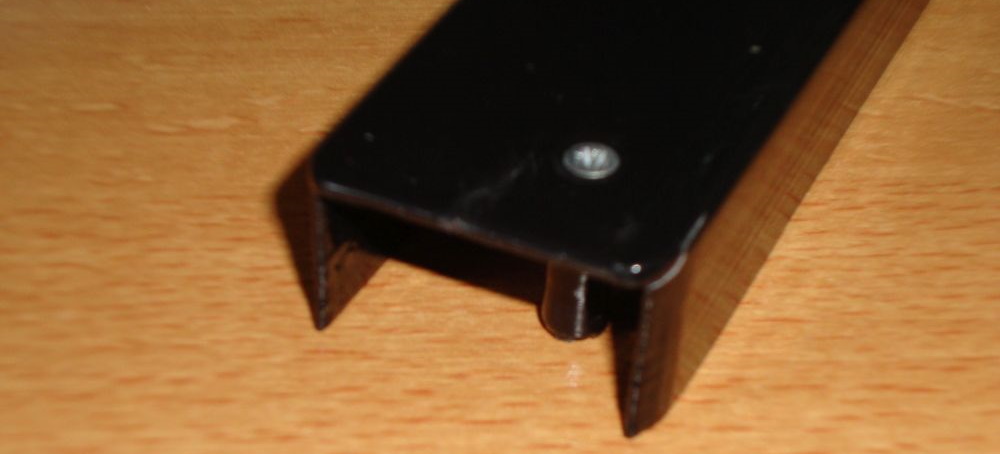
 The lighthammer has a handle, this holds the wiring and the switch to detect the hit of the hammer. In order for the switch to be closed there is a small notch on the inside of the handle. There is only a small problem, because this small notch is rather difficult to print directly because of the overhang, it could be printed using support material. But this is better, because it allows for a certain tolerance in the location of the switch. Therefore we need to slightly modify the printed notch so that it will fit into the space reserved for the switch. You can trim the notch down using a Dremel or small vile or knife. Before cutting make sure that you measure twice... I made some marking in the notch using a knife when the rod was placed inside the handle, this way I knew where to cut with the dremel.
It is important that you use a micro-switch that has a strong spring inside, micro-switches for arcade systems come is various shapes and sizes. The micro-switch required for the light hammer measures (plastic body 28mmx16mm (values are rounded to hole mm). I bought these micro-switches in 2015 on ebay (then they were called: Arcade Replacement Parts Push Button Micro Switch For JAMMA MAME Game). The micro-switch is an NO (normally open) switch. Be aware that there are micro-switches available that can be easily activated (there clicking sound is also less loud), these have a very weak spring inside the switch mechanism, this is not to be preferred, because we use the force of the micro-switch to move the hammer back to it's default position. This saves the uses of an additional spring, a part that can be very difficult to obtain in the right shape/strength/size. Normally the spring inside arcade like micro-switches is strong, but if forces are specified, simply choose the one that has the highest activation force. However, there is a way to increase this by adding foam rubber but foam rubber may never be the main "spring" in the hammer mechanism. More about foam further on this page.
 In order for the rod to move nicely inside the handle, the handle is printed slightly too large, this (if not modified) will cause the rod to wobble a little. Now you could say why wasn't the design adjusted for this so that it is printed correctly, the reason is tolerance. It is easier to trim a small rim of plastic from the top of the handle then to trim the entire handle. The tolerances are in the fact that the plastic rod might not be perfectly straight any more after the smoothing procedure, now if this happens to over-smoothed it. Anyway, the action required to make the perfect fit is only a few minutes of work. This because the layers of the print separate quite nicely in the direction the modification needs to be done. However, be careful when using sharp knifes.
The tip of the hammer
 The tip of the hammer is made from soft foam, which is nothing more then isolation foam for 12 mm tubing/plumbing. Available at many hardware stores in the perfect color for this project... metal grey. The hole in the middle of the foam is very useful, because that is where our light sensor will be located. If this hole wasn't there, we would have to make it ourselves and that would never have looked as nice.
Cable strain relief
 Very important is a good strain relief on the cable. First place a strong tie-rap on the cable, this will prevent be able to pull the cable out of the hammer. Second use a generous amount of hot-glue over the end of the cable. This prevents the cable from being forced into the hammer and any movement of the wires. Important as this movement might otherwise cause damage to solder joints. Also use hot-glue to secure the micro-switch in place, so that it will not move up and down.
Tuning the activation force of the hammer
 If for whatever reason the lighthammer does not have a satisfactory feel when "hitting" the screen, then additional damping material or an additional spring-like force may be required. Which can be achieved by using rubber-foam, for instance the type that is used in all sorts of mattresses. Cut a small piece of foam and place it near the end of the handle. There is the most room AND it will be the most effective. The foam rubber dampens the hammer motion, so it feel less like a plastic hammer during a hit. It also reduces the effect of the wiggling of the rod inside the handle. And perhaps most importantly it increases the activation force of the switching mechanism. The latter may be of use to everyone who finds the hammer to be to sensitive. A small benefit to this sollution would be that the end of the handle is no longer open, because the foam now seals the opening that would otherwise be visible when the hammer is in the "resting position". The foam will not only make it look a little nicer (even better if colored black using a black marker) it also prevents dirt from entering the mechanism.
The electronics
The easiest way is to use a special sensor is an OPL800-OC (Datasheet of OPL800-OC) in 2015 this was a widely available sensor (Digikey, Mouser). The beauty of this sensor is that it holds an internal amplifier, which makes using it very easy (because we do not need to add any other components). The OC in the typenumber stands for "open collector", this is required because if you don't use this type of output then it will cause problems in combination with the keyboard (although you can always put a small Shottky diode in series with the output of the sensor). You can find more information about how to fix this on the lightgun page of my website. HOWEVER... because the OPL800-C can be difficult to obtain for lot's of people AND because it might be even more difficult in the future, I decide to base the design one of the many more common photo-diodes and adding a simple amplifier circuit. All the parts are general purpose parts and if not available could be substituted by a similar component. If you are capable of building an SMD circuit, then you are capable of finding replacement parts. For more information, see the schematic in the download section below.Placing the electronics inside the hammerhead
 The lighthammer uses a very sensitive detection circuit and depending on the TV/monitor used some interference may be picked up from the TV/monitor, this interference may cause problems with the detection of the light from the TV/monitor. The only way to shield the circuit from this interference is by encasing the circuit in properly to ground connected adhesive copper foil or aluminum foil. It is very important that you make sure that this is electrically connected over a as wide as much area to the GND of the circuit. The easiest is to use some copper foil , so it can be secured/connected to the PCB using solder. In case of aluminum foil it is best to place many small wires between several layers of foil, in order to ensure a good electrical contact. Depending on how neatly you do this this may work for many years without problems... or not at all. For some of you copper foil can be difficult to obtain (or simply too expensive, although you only need a few cm, it is mostly sold on a roll holding 5 or more meters). If you have a small piece of copper or brass tubing laying around, and it is not too heavy, you can also use that although adding the extra weight to the design might cause problems in the long run. On the image below you see the light-diode shielded by the copper tape, soldered onto the PCB, this way the sensitive light receiving part can see the light from the front but is insensitive to the electrical noises from the television or monitor tube. The PCB itself is not required to be shielded because of the ground plane already covering the entire bottom layer of the PCB.
 With all the wires soldered to the PCB, we can mount the PCB in the hammerhead, it is clamped between the foam and the printed "bezel" creates a nice cover on the front of the hammer. This "bezel" is to be glued in place, I used hot glue. So if needed I could remove it relatively easy without damage to the PCB. The PCB is clamped between the foam and to create some space for the wires I removed some of the foam near the end. The PCB has many sharp points one one side, which press into the foam. This should prevent it from sliding during the hitting action, and the large flat surface on the bottom of the PCB prevents it from rotating. Now gently slide the whole assembly into the hammerhead and glue the head in place. I used cheap hobby glue, so that if required I could take it apart again, I did not use hotglue simply because that would be too thick but also because I was afraid that the heat might deform the hammerhead. Being the whole print is done using ABS, I could have used acetone, but that might have left stains if not done properly but more importantly, I would never been able to take it apart if really needed. And because the things I tend to make are never right the first time. So, being able to take things apart again is very important to me.
Failed prototypes
 Although the Lighthammer seems like a simple device, this doesn't mean that it was right the first time. Many design iteration s were made to get to the final result. Many badly designed prints, many wasted hours and not every print was successful for other reasons so some had to be printed twice... only to find out later that it wasn't really what I wanted. The image from left to right: it all started with a rubber design (a 70 cent dog toy) and almost a year after that I made a wooden test version of a design that no longer required the buggy homemade accelerometer. A version was printed from ABS with a very clever (at least I thought it was) design that printed the hinge. But as it turned out the switch (or pivoting point) needs to be as far away from the hammerhead as possible. Otherwise it doesn't feel good, a hammer should be solid, if the head moves too much it doesn't feel realistic. So from there a design with a long lever was created... and cancelled directly after. Then I had a really bright moment, the handle must be sturdy, so the head can be glued onto it and it won't break no matter from which side forces may be applied. Also by integrating everything in the handle there are no places where wires are bend during the hitting action and no bending of wires means that wearing or breaking of the wires is completely eliminated. Yes... this is a good design. Or at least good enough to be worked out further. So I did that, bought a silver-color roll of ABS and started printing. It took some time to get to this point but I'm very pleased with the result, now everyone who wants to can make a lighthammer.
Programming
Writing software for the lighthammer does not have to be difficult. The location on the screen is retrieved from the registers .. and ... (just like a lightpen) The hit detection is read by ... (just like the trigger of the stack light rifle). Please refer to my lightpen webpage for more detailed information. The main program loop would consist of checking of the hit detection (trigger) signal. Only when this occurs the position of the hammer on the screen is to be read in order to check for a hit/miss. Check out the source code, it has lot's of comments.Downloads
These links contain a game in a playable .PRG format together with the complete source-code. You may play these games with a lighthammer OR with a lightgun that is compatible with the "Magnum light phaser" or the "Stack light rifle". Have fun, but don't expect too much, they are just simple games. However they may not look like much, they are great fun to play.Everything is programmed in CBM Program Studio, a development environment that is easy to use and have lot's of features. It includes sprite editor, character designed, screen builder. It is great for BASIC and it is great for assembly programming. So if you like to program for your Commodore computer (doesn't matter if it is a C128 or a PET or everything in between) you should really give it a try.
STL files
Feel free to improve upon the lighthammer design and if you decide to share the modified design then please mention my name. For those who directly want to get to the printing, there are also the STL files, ready to be sliced and printed.
Lighthammer_3D_printed_parts.zip (FreeCAD lighthammer design files and the 3D printer ready files)
Schematic & PCB
LighthammerSchematic.pdf (this is the schematic of the sensor PCB, it also includes a short description of how to connect the micro-switch)
Lighthammer_gerber_files.zip (these are the files required to order a PCB from a PCB supplier, I ordered my PCB's from Seeed studio using their PCB service, these files are best viewed using the gerber viewer "viewmate". For some reason a lot of online gerber viewers cannot show these gerber files correctly don't ask me why. The gerber files themselves are 100% correct, I've made them in the same way using the same rules I've been using for more then 15 years. I use the CAD package named "Accel" which is an aging PCB CAD program, though it has never obstructed me in any way regarding PCB ordering no matter what PCB supplier I ordered from).
Games:
C64_smack a mole_V2.zip This game is what you'll you see on this website and in the YouTube. Below a screenshot showing how smack a mole looks like, not shown is the winter mode. The winter mode is a much more brighter screen using with lot's of white, which might help when playing the game using a lightgun.
C64_hit the buttons.zip This game looks a lot like the game SIMON. And regarding the game play, it is identical. The main difference is the shape of the playfield. I made a square playfield instead of a round one, the main reason for this was that a square playfield is much easier to program using the PETSCII character set.