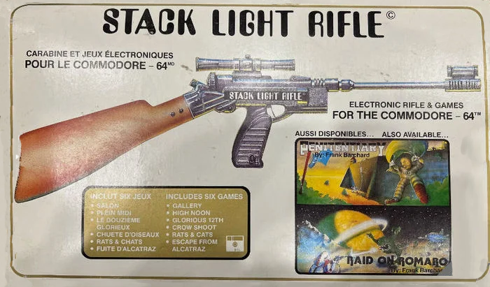
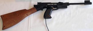
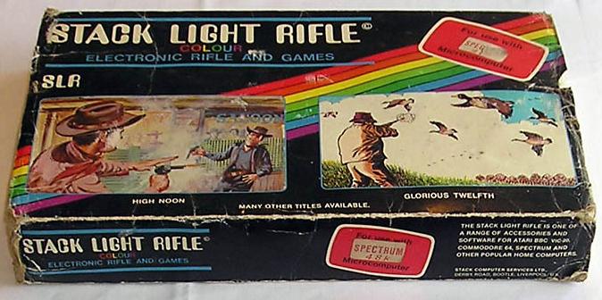
 This model was produced many times and under various different brand names sometimes with tiny modifications to the mold to add a different name. Or perhaps an entirely new mold was made, or various molds were made from the beginning, who knows. One thing is certain there are many versions that all look alike, a lot.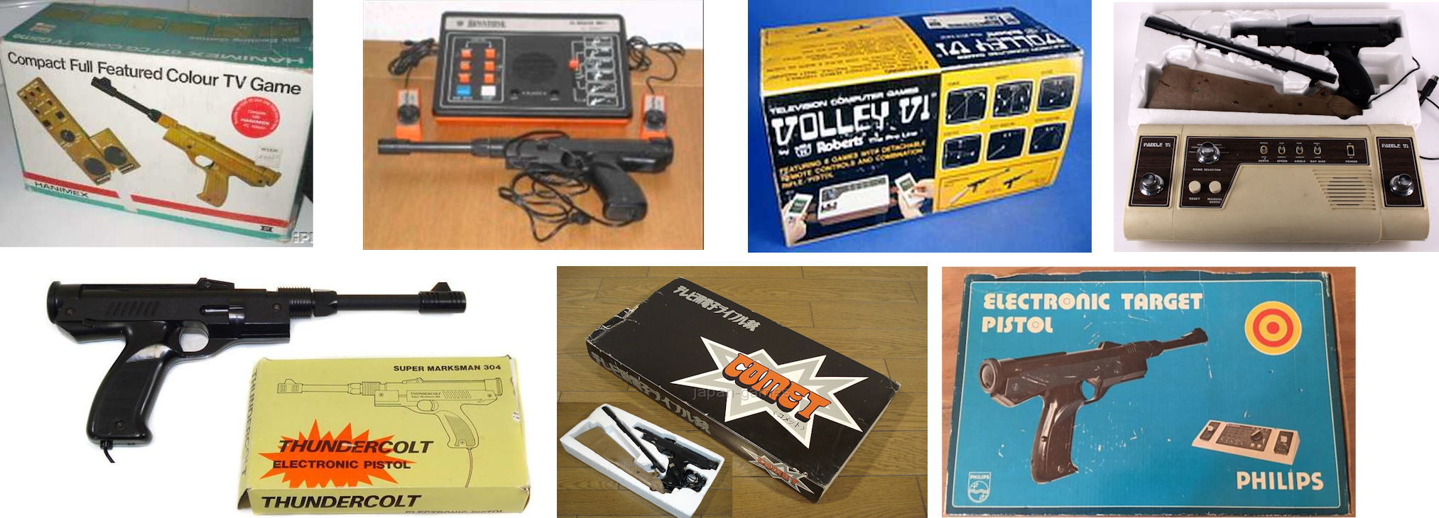
The Stack light rifle:
This lightgun may not look as real as the gun included in the "Magnavox Odyssey Shooting Gallery" pack, it sure looks nice. It has games for the C64 and the VIC20. Due to the long barrel it claims to be a very accurate gun. Considering the difficulty of the available games you'll certainly need that accuracy. The most interesting part of this is the ability to configure it to your own taste. If you whish you can use it with or without the sholder piece or barrel. There were also versions with a scope and a longer barrel. The gun really feels comfortable when holding it and contributes largely to the gameplay. This gun design also exists under different names for different systems. Below you'll see that my own modified lightgun is build into such a gun.
How to use:
The stack light rifle for the C64 (or VIC20) is a little strange in how it should be connected to the computer. Because this system seems to come with 2 connectors. Although the C64 and VIC20 have all available signals in the joystick port connector, somehow this is not enough for the stack light rifle. The stack requires a power supply that has a higher voltage then the available 5V. Therefore it requires a connection to the userport of the C64 and VIC20. The userport has a 9V AC power supply. This isn't used by many devices but the stack light rifle uses it to generate a voltage of 12V (please correct me if I'm wrong). The 9V AC signal is rectified by a simple 4 diode full bridge rectifier and a large capacitor.
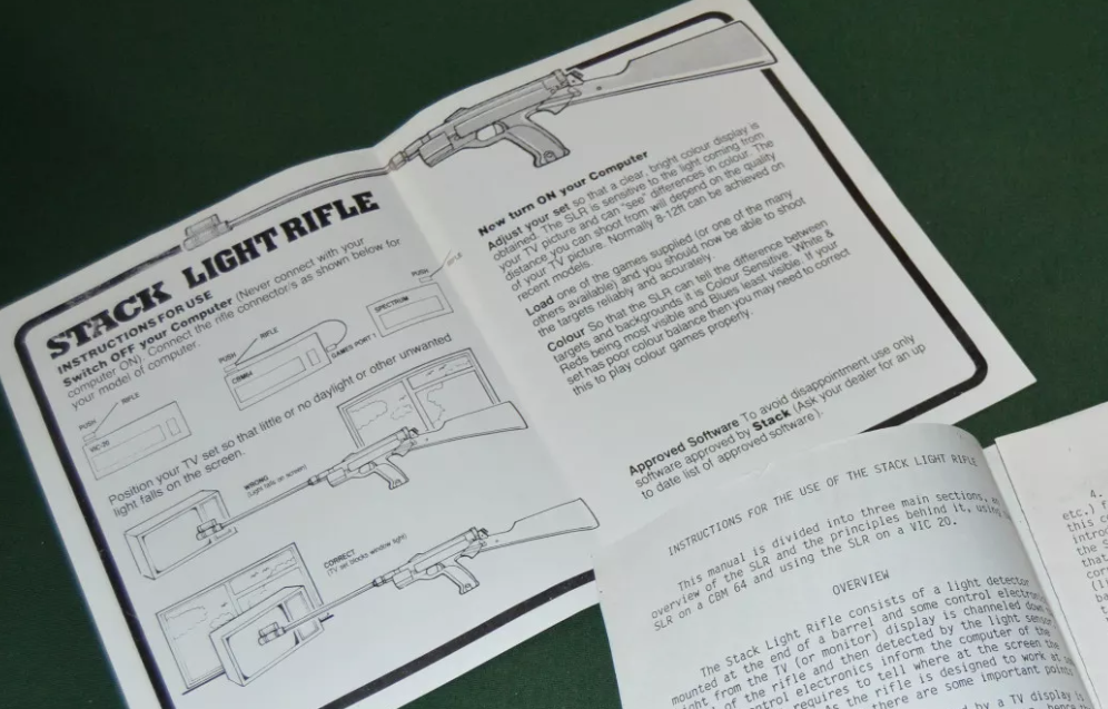
Here is link to the manual in PDF format Stack_Light_Rifle_A4.pdf
Mechanical:
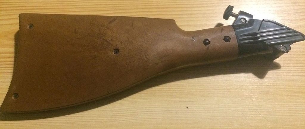
The stack light rifle is a very customizable lightgun. The barrel and stock can be removed, which is practical for shipment in the box, but also allows users to use it as a gun or as a rifle. Just remove the stock and barrel and suddenly your intimidating light rifle becomes a practical and handy lightgun. Unfortunately... things that can be removed often break or simply get lost over time.
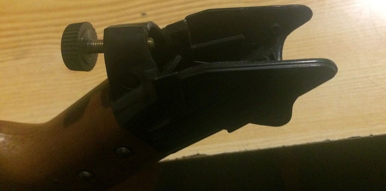
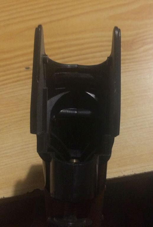
The stock for instance. Below some detailed pictures of the stock and the mechanism to attach it to the gun. For those of you who are handy with wood and plastic... perhaps you can make the missing part based on these photo's.
You may click on the images to download a larger version to get a better view of the details.
Electrical:
The stack light rifle connects to the both the joystick port and the userport.
Joystick port:
Trigger switch is connected between pin 3 (LEFT) and pin 8 (GND)
Light sensor (active low) is connected to pin 6 (LIGHTPEN)
Light sensor circuit power i connected to pin 8 (GND)
User port:
Light sensor circuit power is connected to pins 1,12,A,N (GND)
Light sensor circuit is powered by pins 10, 11 (9VAC)
Light sensor pullup resistor is connected to pin 2 (5V)
Here is the complete circuit of the PCB and cables of the stack light rifle in PDF format SLR_circuit.PDF
Programming:
The X and Y coordinates of the lightpen use the same coordinates as sprites; thus the very first pixel at the left edge of the text screen would have an X coordinate of 24 on a PAL machine (read as half the value, i.e. 12, from the VIC address). See the programmers reference guide for more detailed information. Make sure you sample the lightgun position values more then once. This because the X-position measurement contains some jitter. This isn't emulated by VICE because it is caused by the gun and the person holding it. Also make sure that you offer the option of
calibrating the gun, that is to remove the offset from the position values. Request the user to point to the center of the screen (place a target there) and read the lightgun position values, then you can determine the error/offset. Subtract this offset from your measured positions during the game and you're done.
C64 register $D013 (X coordinate): Holds the X coordinate divided by two. In order to obtain the actual X coordinate (a 9-bit figure), you have to multiply by 2, or do an ASL on the byte obtained from this register, to get the actual X coordinate.
C64 register $D014 (Y coordinate): Holds the Y coordinate.
C64 register $D019 (VIC interrupt reg): Bit 3: LPIRQ, 1 = lightpen has captured a new value and indicates that D013 and D014 are updated (you do not need to use this register, you may read the D013 and D014 at any time and as much as you like)
C64 register $D01A (VIC interrupt enable reg): Bit 3: MLPI, 1 = enables lightpen interrupts (interrupt enable register is used for en/disabling lightpen interrupt in $D019)
Reading the trigger is possible with the following code:
            ;This routine will check the trigger, it will exit with the carry set when the trigger is pulled (and released)
            CHECK_TRIGGER   LDA $DC01
                            AND #%00000100      ;check for fire button of Stack Light Rifle
                            BEQ CHECK_TR_STACK  ;trigger of Stack light rifle detected
                            CLC                 ;clear carry to indicate that the trigger has not been pulled
                            RTS                 ;no trigger pulled, exit routine

            CHECK_TR_STACK  LDA $DC01
                            AND #%00000100      ;check for fire button of Stack Light Rifle
                            BEQ CHECK_TR_STACK  ;keep looping until released
                            SEC                 ;set carry to indicate that the trigger has been pulled
                            RTS                 ;return to the calling routine
My SLR is broken, the X-coordinate is all over the place...:
If you happen to own an SLR and have tested it using an input device tester tool or a lightpen game that shows a cross-hair of some kind, so that you can see where the SLR is aiming at, you might notice that the X-coordinate is all over the place. But the Y-coordinate seems to be just fine. Now you are forgiven to think that your SLR is broken and in need of repair, but this behavior is by design. It is even stated in the manual:
 The reason for this is not exactly known, it might have something to do with the sensor used, which might not be able to react fast enough to register the X-coordinate reliably. But it could also be that the electronics are designed with another system in mind and that this wasn't fixed when sold for use with the C64. If somebody knows the full story, please let me know. The manual is pretty clear about the SLR being a Y-coordinate only device, but for those who are still in doubt, the SLR test software (see here below) also only focuses on the Y-coordinate. If they felt that their device was capable of outputting a valid X-coordinate then they most certainly would have put that information into the test program.
Test software:
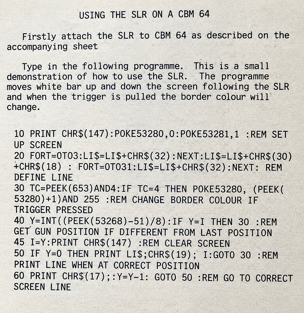
There seems to be a small testing program for the SLR on the C64 as shown in the image below. You may click on the image to download a larger version to get a better view of the details. Fortunately, there is also a disk image you can download: SLR Demonstration CBM 64.prg This may save those who are interested in this program some typing. Please note that this program only shows the Y-coordinate, the X-coordinate isn't indicated in any way, this is because the SLR appears to be an Y-coordinate only device, the resulting X-coordinate is unreliable and therefore not used.
Adapter (SLR-to-MLP):
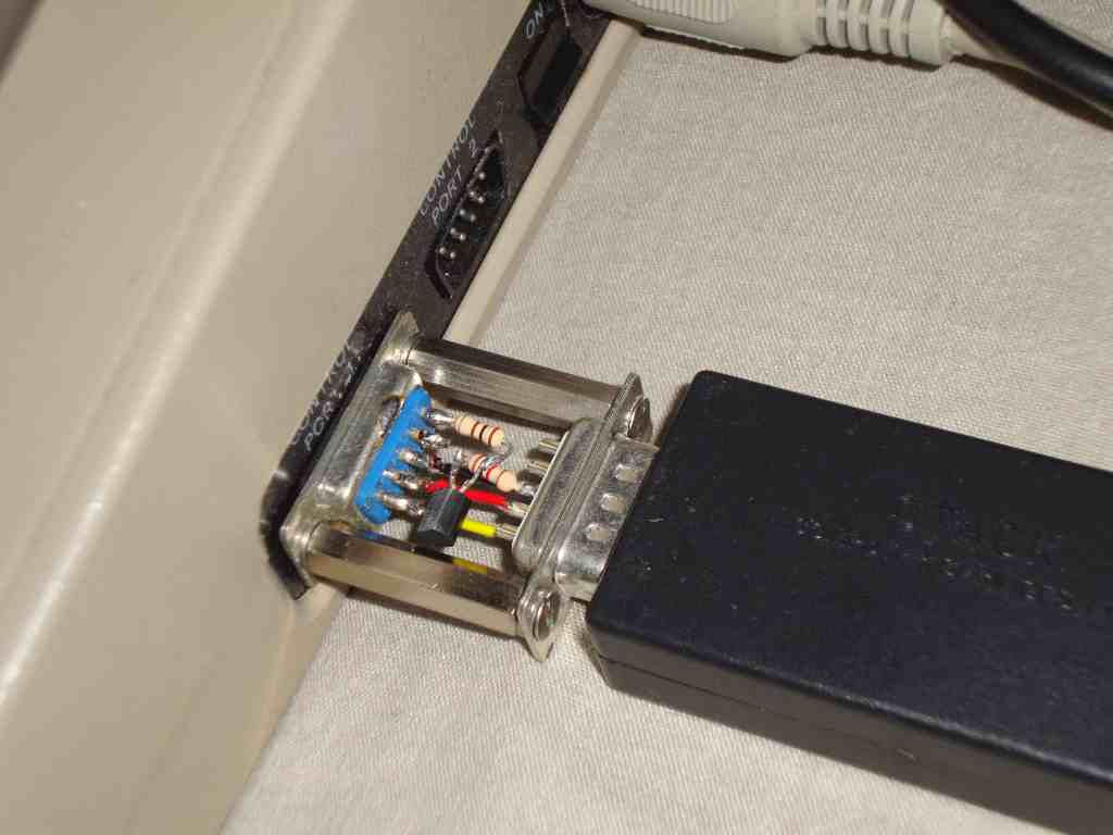
Now the Stack Light Rifle is a great piece of hardware... but it lacks software, so if we could only use it to play games that were written for other types of guns, we could at least increase its usability. So in order to make Magnum Light Phaser games work with the Stack Light Rifle an small adapter needs to be made. It requires 2 resistors, one transistor, a sub-d 9 pole male and a sub-d 9 pole female connector and some wires. Also some screws to hold it all together would certainly help. Below is a photo of such an adapter, which as you can see, is very simply to build. You may click on the images to download a larger version to get a better view of the details.
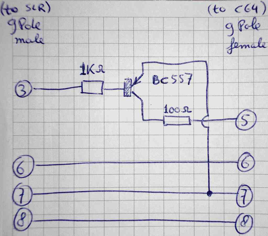
 Here is the schematic of the adapter. As you can see it converts the trigger signal. The trigger signal of the SLR pull pin 3 (which is "joystick left" of the C64's joystick port) down to ground. While the MLP requires pin 5 (which is "Pot-Y" of the C64's joystick port) to be pulled high.
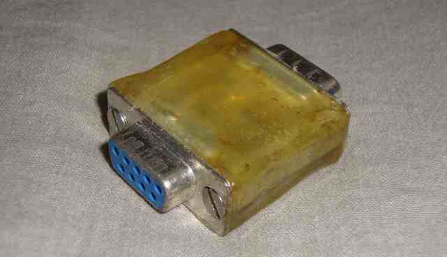
 It is to be advised to cast the whole converter into some hotglue to protect the components and wires, so that they wouldn't be damaged when thrown into a box of C64 parts. Although the whole construction is relatively strong, casting it into hotglue would make it even stronger AND prevents direct access to the wires components and pins, reducing the risk of damages due to static electricity. Now this doesn't make it any prettier but it is a whole lot safer.
Extra images/info:
Because I have more images/info than I showed on this page, I've put them in a .zip file: extra_info.zip