The Magnum light phaser:
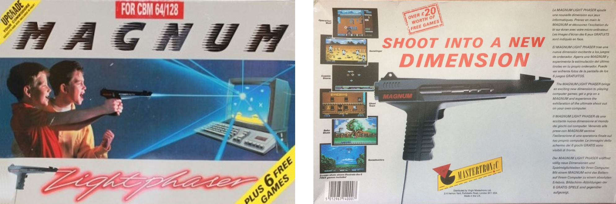
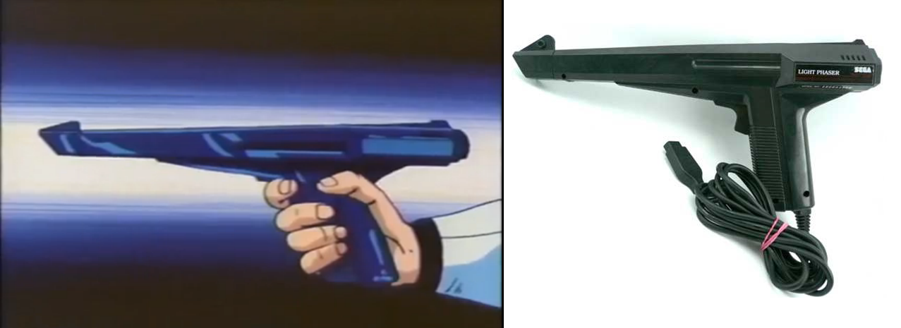
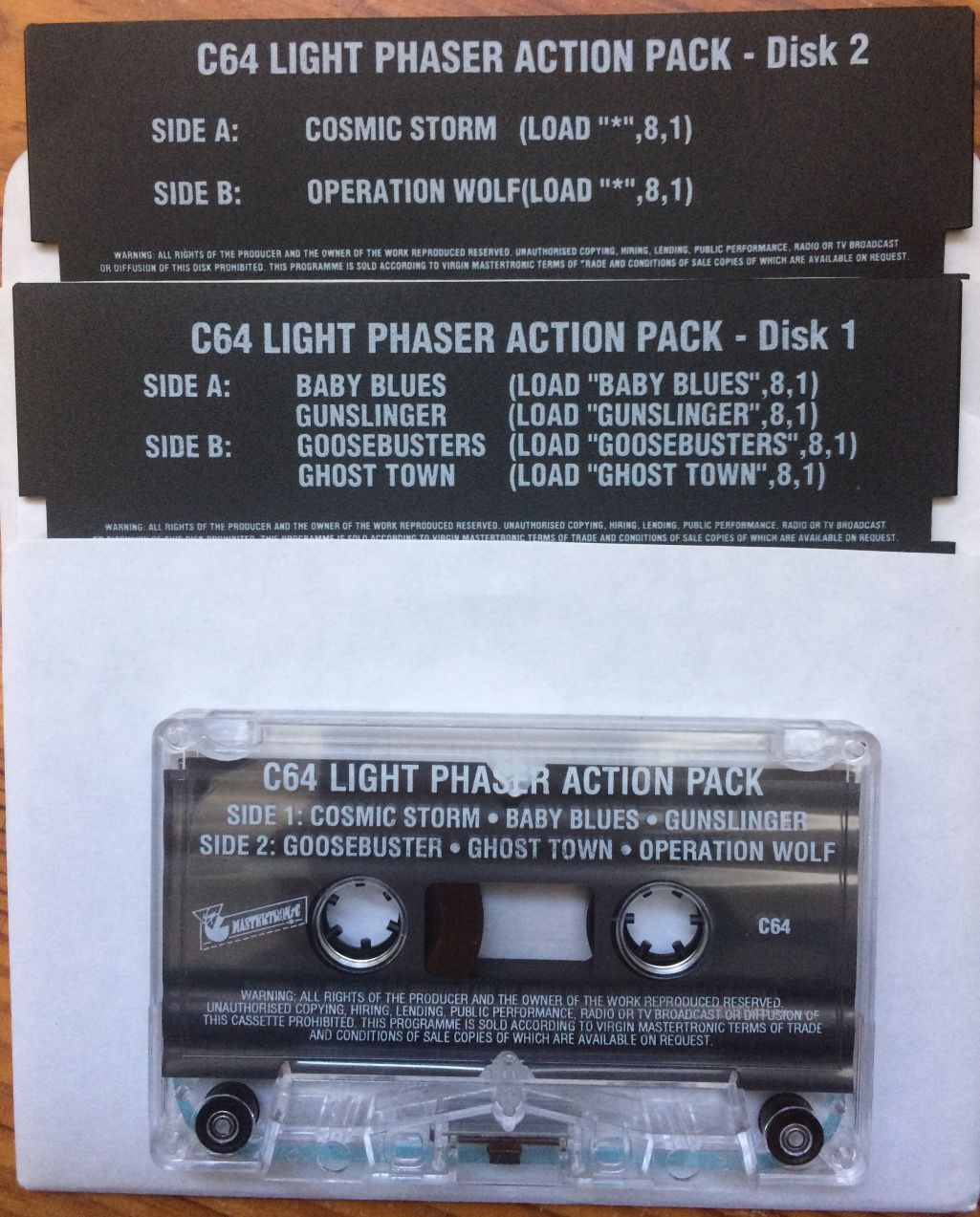 The Magnum light phaser looks a lot like the gun from the anime series Zillion. But regarding those similarities the Sega light phaser is almost a perfect match. Which according to the YouTube video "ZILLION: The Light Gun That Made Sega Millions" (by Nostalgia Nerd) that is not a coincidence. Anyway, the looks of this lightgun are pretty futuristic with all those straight lines, perfect 80's styling.
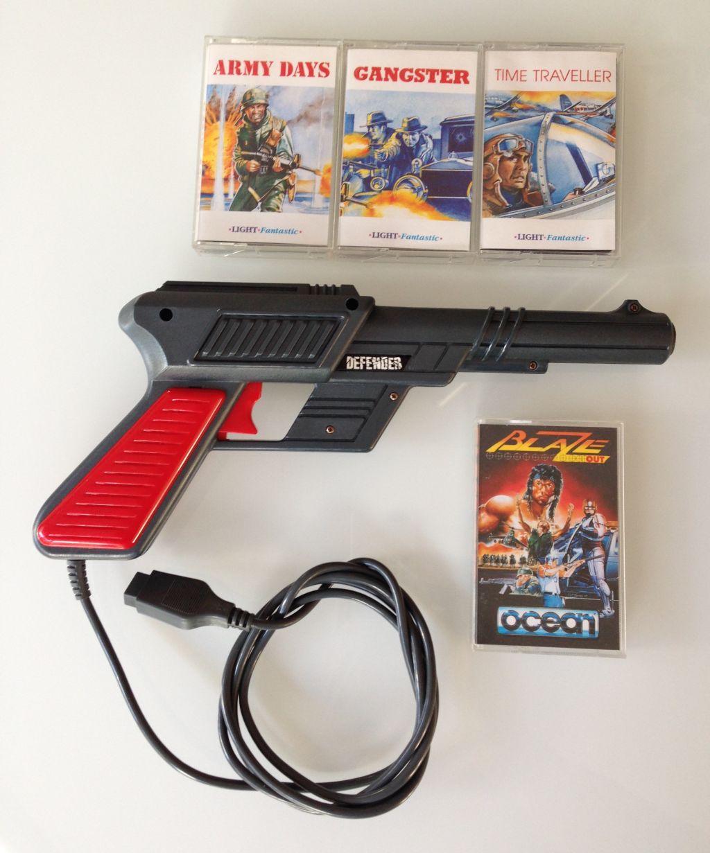
A lightgun that is fully compatible with the Magnum light phaser is the "Cheetah defender" which has also been marketed for several types of machines (for instance the Sinclair spectrum).
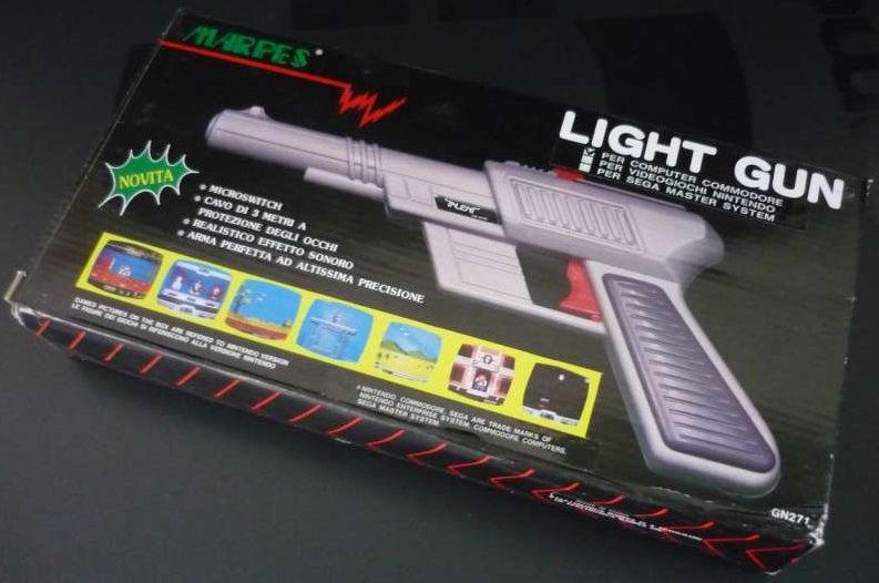
Another lightgun fully compatible with the Magnum light phaser is the "MARPES light gun" which appears to be a cheap. This appears to be also marketed for the NES and Sega. It's interesting to see the box showing screenshots of the game NES game "Wild gunman". Depending on the system it was sold for the wiring and connector would be different, obviously. When this lightgun was opened it seemed to be very well designed. Shielding against interference, micro-switch trigger, lens glued in place, so it doesn't fall out upon opening the gun. Interestingly the handle itself can hold a 9V battery, but for the C64 you don't need this, so this is just an empty place without battery contacts. But this is all very well designed and you cannot directly see from the outside that there is a battery door. You need to slide off the dark grey cover plate of the handle to get to this place. Which you also need to do to get to one of the screws if you want to open the lightgun for repair or inspection. The design even has a 4011 used as an amplifier, which is unconventional but makes sense. Strangely the PCB has the marking ATARI on it, suggesting that the PCB was designed by Atari, but I doubt that they had anything to do with this gun. Unfortunately regarding the electronics it was assembled very cheaply. The metal shielding wasn't properly soldered and fell off when I touched it. The wires to the trigger button where too thin and broke after a few times bending. Now normally you won't open the gun, so there is actually no real problem and it worked perfectly before I opened it, but still. However, I only opened it because I was curious and my curiosity killed it, so I repaired the gun by replacing the trigger button wires and resoldering the metal shielding. And now the gun is in perfect order. In fact it is the most sensitive gun I own.
Electrical:
Trigger switch is connected between pin 5 (Pot AY) and pin 7 (+5V)
Light sensor (active low) is connected to pin 6
Light sensor circuit power is connected to pin 7 (+5V) and pin 8 (GND)
Programming:
The X and Y coordinates of the lightpen use the same coordinates as sprites; thus the very first pixel at the left edge of the text screen would have an X coordinate of 24 on a PAL machine (read as half the value, i.e. 12, from the VIC address). See the programmers reference guide for more detailed information. Make sure you sample the lightgun position values more then once. This because the X-position measurement contains some jitter. This isn't emulated by VICE because it is caused by the gun and the person holding it. Also make sure that you offer the option of
calibrating the gun, that is to remove the offset from the position values. Request the user to point to the center of the screen (place a target there) and read the lightgun position values, then you can determine the error/offset. Subtract this offset from your measured positions during the game and you're done.
C64 register $D013 (X coordinate): Holds the X coordinate divided by two. In order to obtain the actual X coordinate (a 9-bit figure), you have to multiply by 2, or do an ASL on the byte obtained from this register, to get the actual X coordinate.
C64 register $D014 (Y coordinate): Holds the Y coordinate.
C64 register $D019 (VIC interrupt reg): Bit 3: LPIRQ, 1 = lightpen has captured a new value and indicates that D013 and D014 are updated (you do not need to use this register, you may read the D013 and D014 at any time and as much as you like)
C64 register $D01A (VIC interrupt enable reg): Bit 3: MLPI, 1 = enables lightpen interrupts (interrupt enable register is used for en/disabling lightpen interrupt in $D019)
Reading the trigger is possible with the following code:
            ;This routine will check the trigger, it will exit with the carry set when the trigger is pulled (and released)
            CHECK_TRIGGER LDA $DC00 ;Control-Port 1 selected bit7=0 and bit6=1
                          AND #%00111111      ;clear bit-6 and 7
                          ORA #%01000000      ;set bit-6
                          ;SEI                ;Disable interrupts (for instance keyboard scanning)
                          STA $DC00           ;now control-port 1 is selected for reading the POT registers
                          ;LDY #$80           ;Wait a little while so that the analog signal can be converted properly.
            ;CH_DELAY     NOP                 ;However... depending on your program this delay might not be required and may be left out
                          ;DEY                ;and that's why this piece of code is already been defined as commented code.
                          ;BPL CH_DELAY       ;
                          LDA $D41A           ;Paddle Y value 0..255 ($D419=Paddle X value theoretically it is 255=no trigger, 0=trigger pulled)
                          ;CLI                ;Enable interrupts
                          CMP #128            ;in practice the value 0 isn't always reached, so it is better to check a range of values (255-128=no trigger, 127-0=trigger pulled)
                          BCC CHECK_TR_MAGNUM ;trigger of magnum detected
                          CLC                 ;clear carry to indicate that the trigger has not been pulled
                          RTS                 ;no trigger pulled, exit routine

            CHECK_TR_MAGNUM LDA $D41A         ;Paddle Y value 0..255 ($D419=Paddle X value 0..255 )
                          CMP #128            ;keep looping until released
                          BCC CHECK_TR_MAGNUM ;
                          SEC                 ;set carry to indicate that the trigger has been pulled
                          RTS                 ;return to the calling routine
Extra images/info:
Because I have more images/info than I showed on this page, I've put them in a .zip file: extra_info.zip