What is the Commo Pad?
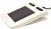
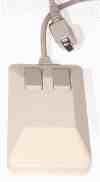
The Commo Pad is a device that is intended to be used on a Commodore 64 computer. It is to be connected to the joystick port, it can act like a KoalaPad, joystick or 1351 mouse. But it can also be connected to the USB port of a PC and act like a regular 2-button and scrollwheel mouse. The Commo Pad is based around a cheap and relatively easy available 4 wire resistive touchscreen. This means that it can only detect one object on the pad AND it requires a "significant force" for accurate control. However, generating enough force is no a problem when using a stylus. A blunt plastic object incapable of making scratches on the surface. But in case of an emergency you can always use the back of an ordinary plastic ballpointpen (never use the tip of a ball point, you'll damage the device in multiple ways).The Commo Pad has 3 buttons. When connected to a C64 these buttons can be used to configure the device to one of the 3 modes. Holds the button for the desired mode while turning your C64 on. By pressing the top button while switching the C64 on, the koala mode is selected (mode 1).
By pressing the middle button while switching the C64 on, the joystick mode is selected (mode 2).
By pressing the bottom button while switching the C64 on, the 1351 mouse mode is selected (mode-3).
After changing the mode setting of the device, this will be automatically stored, so the next time you turn your C64 on, the Commo Pad will operate in the mode you selected earlier. In order to indicate the mode used, the Commo Pad will beep 1, 2 or 3 times depending it is in mode 1, 2 or 3. The meaning of the number of beeps is printed on the background of the touch area.
The touch area has a circle in the middle, this is to be used for the joystick mode. Although the joystick mode uses relative position changes, it may help to use the absolute center of the touch pad. This way you have an indication on how far you need your stylus to move in order to generate a joystick up/down action. However, the joystick mode is more of a gimmick that that it has practical value. Because when playing joystick games, you really want something to limit your movements. This is something that a touchpad cannot offer. Although a cardboard template could be made to limit the movements on the touch pad, it will remain difficult to return the stylus to the center of the movement circle.
 The device automatically detects whether it should be in USB mode or in C64 mode. Simply by sensing the power source. When it is connected to the USB port, it will act like an ordinary PC mouse. When the 5V of the joystick port is detected, the device goes into the C64 mode and will act like one of the 3 possible devices (KoalaPad, joystick, 1351 mouse).
How did I make the frame?
3D printing is nice... but nothing is right the first time and if you do not know exactly what you really need then 3D printing can be a waste of time (especially considering the size of the frame and the time it takes to print the first draft version). Therefore, sometimes it's easier to just take some scrap pieces of wood and a fresh bottle of glue and see how it goes from there. It took me about a weekend of tinkering to get to this shape, then a day of sanding and priming and then another day of painting it to the desired color. Now did I save time compared to 3D printing, who knows. But what I do know is that it was nice to get away from the computer for a few days. And that the end result doesn't look like a 3D printed or wooden part.
Why did I create it?
 When I discovered that resistive touch panels (meant to be used in combination with modern LCD screens of the same size) were relatively easy to buy and fairly cheap. I started to imagine how it would be like to use such a touch panel for controlling my PC and C64, instead of a regular mouse. Wouldn't it be nice if you can build a KoalaPad for your C64 with modern components? This all seemed like a nice excuse for me to buy such a panel and play with.
So I bought one, waited a few weeks for it to arrive and when it came in I realized that such a panel was useless without a decent frame (to prevent it from breaking) so I glued some pieces of scrap wood together but wasn't quite satisfied with the result of the contraption, so this quickly ended up in a corner of the room. And then quickly forgot all about it... many months later when I cleaned up that particular corner of the room I decided that it was time to make a decent frame for it. But in a way that I could safely experiment (without breaking the glass panel or breaking the delicate wires). I used it in combination with an Arduino Pro Micro.
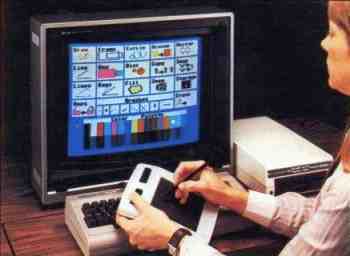 The initial firmware start was actually pretty easy, considering I could use the basic mouse example with only a few modifications combined with a touchscreen library I found in some dark corner of the internet. Which meant that I could go straight to the details of the user interface. We really live in a great time and age where we can benefit from the great libraries that are available for the entire Arduino community. So with the PC part being functional I could now dive into the retro computing part. The part that actually matters regarding this project. This is also the exiting part (from a technical point of view). My intention is to make it work like a KoalaPad and perhaps even like a 1351 mouse if all goes well (spoiler alert... it did go well, very well actually). For those who never heard of a koalapad, the koalapad is the famously forgotten input device of the 80's. It could have revolutionized the world, the way we work with machines, but the mouse took over. The image here on the right shows someone working with the koala paint drawing program. Holding the pad a bit strangely, but I guess that's all to get it into the center of the image. Anyway, the KoalaPad acts like a set of paddles BUT is in fact much more then a pair of overlapping resistors. Inside the device is some logic controlling it all.
And as soon as a KoalaPad mode was implemented, a joystick mode followed and then the obvious 1351 mouse. And the name of this project, well... I could not name it KoalaPad II, that would be confusing, misleading etc. So because I made it initially for the Commodore 64 and because it is a pad, the name Commo Pad came to mind. Mostly because it sounds a bit like koala and because this name didn't come up in a google search.
Is it useful?
Actually, yes. It works pretty well. And in both modes, USB and C64. But since the touchpad doesn't detected pen pressure very well, you still need to click a button. This means that you must work with two hands. One hand on the buttons, the other on the pen. Not a big deal, but a major disadvantage when compared to an ordinary mouse. So I'm imagining by solving that by making a simple "pen" that does have buttons (perhaps a button in the tip). This way clicking can become much more natural simply by pushing harder on the pen until you hear/feel a click. But it's very likely that I never will, because there are some many other interesting projects. And to be honest, I still love my everyday mouse and I'm not intending to use a pad at home and a mouse at work or vice versa. And build another one, neh... not now. But despite that pen/button thingy, the KoalaPad had the same problem, so this pen with a button whish is actually more intended for regular PC usage and not for the C64. Although I am pretty sure that the C64 user experience improves just as much.Technical info
Because the C64 is an old lady, that needs to be treated with care and respect. But also because replacement parts are becoming expensive and sometimes hard to find. We need to take some precautions, in order to prevent damage. And the greatest danger is always during development...The device connects to the joystick port of the C64, now technically the joystick port pins (for: up/down, left/right, fire) expect signals that are pulling down. So a line connected to ground (via a switch) or open. In other words, it's just designed to connect to simple switches. Now the Arduino Pro Micro has a sort of 3-state IO-pins. Two states are the logical output states (0V (low output), +5V (high output)) and the third state is the high impedance state, which can be created by setting the IO-pin to input. The IO-pins used are not open collector, but by careful programming an open collector situation can be faked. Just toggle the pin between output (with value 0) or as an input (to simulate the high impedance situation). Therefore technically it can generate the required open-collector behavior the C64 expects and everything will be perfectly fine. However... accidents do happen... especially during development. And we do not want to apply the +5V from the IO-pin directly to the input of the C64. Because this input pin is directly connected to a CIA chip, and those can be easily damaged. So knowing myself, I decided that is was perhaps a bit better to actually make a true open collector IO-connection for the joystick port lines UP/DOWN/LEFT/RIGHT/FIRE. This way nothing can go wrong and therefore I do not have to worry about anything when I work on the firmware of the Arduino. Regarding costs this only adds 5 transistors and 5 resistors to the bill-of-materials which is nothing compared to the costs of the entire device or the costs of the repair of my C64 (which always happens at the most inconvenient moment). And even though you could argue about the real dangers and the limits, adding a handful of transistors does help me sleep a little bit better at night, knowing for sure that a programming error the next day won't fry my precious relic of the past.
The ADC of the POT inputs is able to handle a direct connection to +5V, so technically we do no need to worry about protection (other then ESD perhaps) on that pin. However it doesn't hurt to add a resistor to limit the current a little bit, therefore between the POT pin of the C64 and the IO-pin of the Arduino is a 100 Ohm resistor. Although technically the IO-pin of the Arduino would be the real current limiting factor.
Paddle or POT ADC programming tips
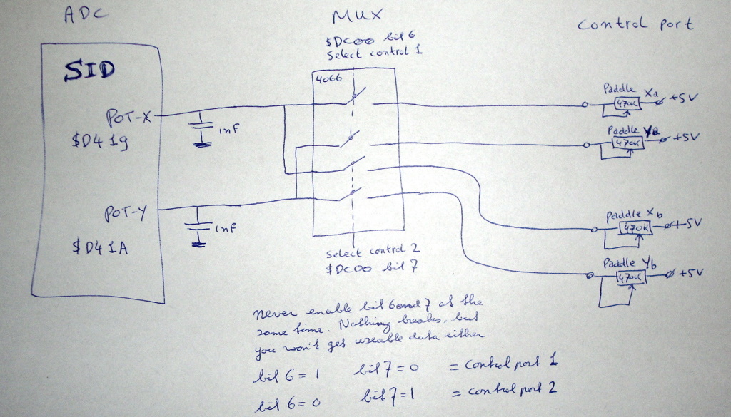
Below is a table of registers that are important for working with the paddle / POT inputs.
| Decimal value | Hex value $ | Specification | Status |
|---|---|---|---|
| 56320 | $DC00 | Control-Port 1 selected | Control-Port 1 selected (bit7=0 and bit6=1) Control-Port 2 selected (bit7=1 and bit6=0) |
| 54297 | $D419 | Paddle X value | bit7...0 = value range 0..255 |
| 54298 | $D41A | Paddle Y value | bit7...0 = value range 0..255 |
| 56321 | $DC01 | Paddle in port-1 | Paddle X fire button = bit2 (0=Firebutton pushed) Paddle Y fire button = bit3 (0=Firebutton pushed) |
| 56320 | $DC00 | Paddle in port-2 | Paddle X fire button = bit2 (0=Firebutton pushed) Paddle Y fire button = bit3 (0=Firebutton pushed) |
 This means that the programmer must first select the control port (also known as joystick port). Then wait... Because conversion takes time and we do not know where the free running ADC is at this moment, it might be in the middle of a conversion while we changed the source of the input. So if we would read the value from $D419 or $D41A directly after selecting the channel, we would get invalid data. So we must make sure that we allow for a full measurement cycle to have taken place which takes 512 us, but we must be aware of the fact that we have to wait out for the invalid conversion to be completed, which also takes 512 us. Because the discharge cycle is of no big importance (but only as long as we know for sure that there is no additional capacitance added in the paddle itself).Therefore we should wait for at least 2 measurement cycles which would be 1024 us, because this way we know for absolutely for sure that a full discharge cycle and a complete measurement cycle has taken place.This delay is no big deal if you are only interested in the data of one controlport, because then you'll only need to change the mutiplexer setting once and wait once.
 But if you are constantly changing the controlport multiplexer this IS a big deal, so it would be wise to program clever in order to save precious CPU time. You might be tempted to have a delay of only 512 us and you'll see that it also works most of the time. Although you will encounter a false value from time to time because of an unreliable conversion. So therefore always wait for 1024 us after changing the control port multiplexer settings and you'll be fine no matter what you have connected to your control port. Now you must not forget to disable the keyboard scanning (one way would be to disable all interrupts), because the keyboard also uses the lines from $DC00 bit 6 and 7. Meaning that the keyboard scanning heavily interferes with the POT multiplexer!
POT ADC inner workings
How the ADC connected to the POT lines in the C64 work? Well this ADC isn't an ADC you'll find in modern equipment. This ADC can not really convert a voltage, it's more a conversion for current.And it does so by measuring the time it takes to fill a capacitor to a known value. Now the ADC logic is inside the famous SID chip of the C64, the capacitance required is outside the SID chip and has a value of 1nF. Below is a very simplistic schematic of the ADC. You can see the counter with increments every microsecond, you can see the comparator for detection of the thresshold level and you see the discharge circuit.
 Basically, it works like this: the longer it takes to charge the capacitor to it's thresshold value, the lower the current coming from the paddle must have been. So for a value of 0 of the ADC, the potentiometer of the paddle must be set to a position with a low resistance and vice versa. Technically this is very easy to implement. Because in the hardware all you need is a set of timers and something that can act like a discharge switch. The ADC (which in a C64 is located inside the SID chip) has basically two states, the discharge state and the measurement state. The discharge state has a duration of 256us and is nothing more then a period of applying a small load to the capacitor and therefore effectively discharging it in a safe way.
Note: the discharge state is not a short, because if it were things might get ugly when the user would tie the pot input to the +5V line, which could very easily happen because real paddles are nothing more then a potentiometer tied between the +5V and the POT line. The discharge cycle takes a fairly long time (256 us) this to ensure a proper discharge.
This was a wise decision of the designers of the ADC, as it allowed to increase the capacitance to the POT line by placing an additional capacitor in the paddle, if this was to be desired. This may be helpful to reduce noise or to compensate for potentiometers that would otherwise have a resistance that would be way too small to be practical.
The measurement state, is nothing more then a counter value being captured when the capacitor's voltage passes through the trigger thresshold. So at the beginning of the measurement cycle, the counter is reset and every us the counter is incremented by one. As soon as the voltage over the capacitor has reached the trigger level, the counter value is captured and we have the ADC value. If the counter reaches the value of 256, the max has been reached, no matter if the capacitance has reached the thresshold, the ADC value will be 255 and the measurement cycle is complete. Followed immediately by the discharge state and it all repeats itself over and over again...
Below is a visualization of what you would see if you would measure the voltage at the POT pin of the control port. Shown are 3 situations of the paddles position, max, center and min. This is a sketch, not a scope image, therefore keep in mind that the charging curves are not exactly like the real thing but the sketch is good enough to show the principle.
 Creative use of the POT ADC (forcing the ADC value)
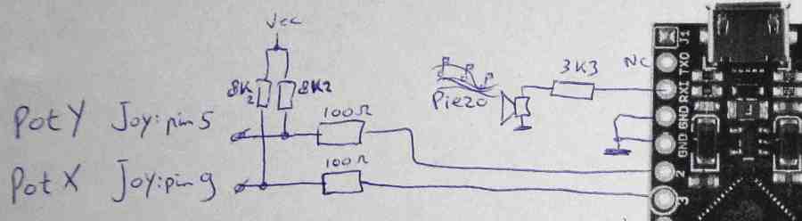
So now we know how the POT ADC works, we can (just like the KoalaPad and the 1351 mouse do) connect other things than ordinary potentiometers. Because if we can detect the discharge state, we know when the measurement state happens and this means that we can control the moment the trigger level occurs by quickly bringing the capacitor to it's thresshold voltage. So technically the device will be forcing the POT-X or POT-Y registers to the desired value. And this is how you can do that with any microcontroller, though it is important to use a microcontroller with a decent set of timers and interrupt capabilities. For a single POT channel is required: one IO-pin, two resistors and two interrupts. Below is a part of the Commo pad schematic related to the ADC.
 Now all the firmware in the microcontroller needs to do is:
- Set it's IO-pin to input, the pull-up resistor of 8K2 should make the input a logical 1.
- Setup the microcontroller to generate an interrupt on the falling edge of the same IO-pin.
- Now when the discharge state happens, the IO-pin will be pulled down, this results in a falling edge and the interrupt will trigger.
-Inside the interrupt we set the IO-pin output with a logic value of 0, this prevents the IO-pin from charging the capacitor once the discharge cycle ends.
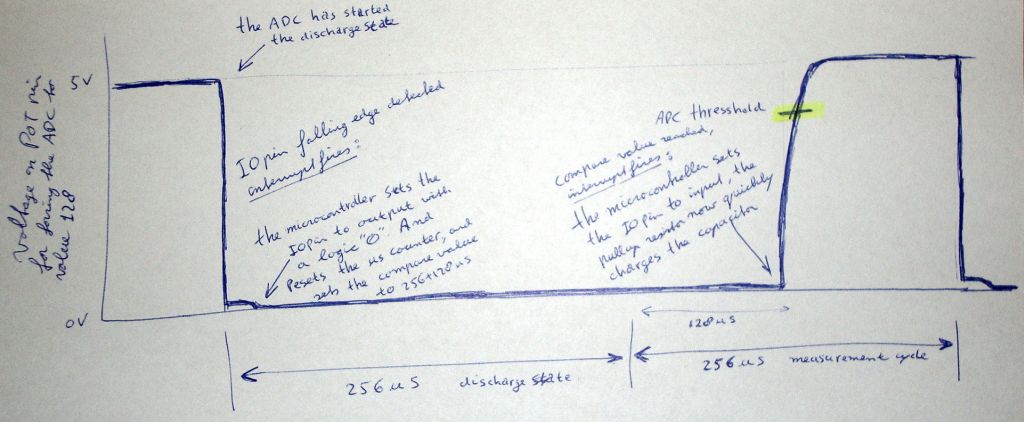
- In the same interrupt we also reset atimer that can count microseconds and we define the capture compare register of that timer to trigger after 256 us (the duration ofthe discharge state) + the required ADC value (for example: if we want an ADC value of 128, we set the compare register at a value of256+128=384us).
-And last but certainly not least, we enable the capture compare timer interrupt to fire when the compare value has been reached.
-When the compare value has been reached, the capture compare interrupt will fire and from within that interrupt we will set theIO-pin to input, so that the 8K2 resistor can charge the capacitor(the careful reader most likely wonders that this charging also takes some time, but considering that that time is very well known we can compensate for it by reducing the compare value slightly,it's just an offset).
With the IO-pin set to input we are back to square one (the cycle is complete) and are capable of detecting the discharge cycle of the next measurement. Completely ready to start the next cycle for the next measurement. Below is an image of the voltage on the POT pin of the control port.
 Fortunately, the POT-X and POT-Y ADCs are synchronous, meaning that they discharge at exactly the same time and therefore measure at exactly the same time. This is great because it allows us to combine multiple functions(required to control the two pot values X and Y) into the same interrupt. Thanks to the excellent timers inside the ATmega32u4 microcontroller on the Arduino Pro Micro we can even use a single timer for the two required timer compare values. But for those details please check the firmware or download the ATmega 32U4 microcontrollers datasheet.
How the koalapad works
 The KoalaPad is an absolute pointing device, the position of the pen on the pad corresponds directly to a position on the screen of the computer. The KoalaPad, sends it data over the POT-X and POT-Y lines of the control port (a.k.a.joystick port). It has a range from 0-255 for both the X and the Y channel of the touch pad. This means that the data can be send directly over the POT wires by forcing the digital value as described above. This also means that any program that can use the KoalaPad can use paddles. There is no technical reason why you can not control a program written for the KoalaPad with paddles, sure it would be far from practical, because you'd be controlling the program (for example koala paint) like an etch a sketch.
The 1351 mouse
 A mouse is by definition a relative pointing device, meaning that it sends changes in position, rather then a position itself. It effectively can sense speed and direction. And it does this with two encoder wheels,one for the X and one for the Y direction. These encoderwheels are driven by a ball at the bottom of the 1351 mouse. These encoders are read by a chip in the 1351 mouse, this chip uses these pulses to in- or decrement a 7bit counter. The mouse sends it's data over the pot lines by forcing the digital value as described above. The X and Y counter values from the chip are send directly. To reduce noise/jitter in the forced POT value, the least significant bit of the POT value is to be discarded by the mouse-driver in the computer for both X and Y. And the POT value has only a range from 64 to 192.
So,this basically means that all the mouse-driver in the computer has to do is to compare the previous ADC value for the X-direction and compare it with the current value, when it increments, the mouse moves to the right and vice versa. Sure there are some challenges because the counter wraps around in both directions, so this may cause problems, especially for fast movements, but this can be detected and there fore does not have to be a big problem. But technically, for normal usage, it doesn't really matter how fast the mouse driver reads the POTvalues, because the position changes and direction can always be calculated by comparing with the last read value. However, for a decent user interface experience, it is important that this sampling of the position value should be done at a reasonable and regular interval.