Restore key does not function properly
So in the end it had nothing to do with the keyboard, unfortunately the keyboard took all the hits, sorry keyboard. When the capacitor was replaced by a functional one, the restore key worked like a charm. It functioned like the good people of Commodore intended it way back in the early eighties. Problem solved.
If you ask me if this is a common problem, I would like to say no, I never heard of capacitors breaking due to age. I assume that this specific model has been subjected to mechanical stresses. I would not be surprised if I would be the cause of that.
Restore key reset hack
 For
my "smack-a-mole" arcade cabinet I wanted a reset button, but I didn't want to drill a hole, this because I forgot about it until it was too late. But also because I do not want it to make it to easy to reset the cabinet when it is on display on meetings. So I knew about the restore button reset hack and decided to go for that. It is a very simple and great hack. I can recommend it to anyone who want to add a reset to their system, it simply saves the cost of a button and more importantly, it saves you from damaging your C64 case.
For
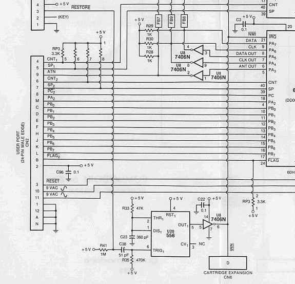
my "smack-a-mole" arcade cabinet I wanted a reset button, but I didn't want to drill a hole, this because I forgot about it until it was too late. But also because I do not want it to make it to easy to reset the cabinet when it is on display on meetings. So I knew about the restore button reset hack and decided to go for that. It is a very simple and great hack. I can recommend it to anyone who want to add a reset to their system, it simply saves the cost of a button and more importantly, it saves you from damaging your C64 case.A 5VDC and 12VDC Power supply (instead of 5VDC and 9VAC)
Commodore has put some clever thoughts into the design of their power supplies. The way the use 9VAC to get 12V for the SID and 6V for the cassette is brilliant. This design is clever in that it reduces costs of wiring, minimizes power loss where possible. The 6V for the cassette is created by half wave rectifying the 9V, therefor it does not create a voltage that is way too high but a voltage that's close to 7-8V. This is stabilized by the same transistor that switched the cassette motor. Anyway, although it is a nice design, it is very annoying if you do not have 9VAC. My Arcade cabinet has 5 and 12V and all DC. And I do not want to put in another power supply to get the 9VAC. So I needed to do some modifications. I made these modifications while referring to the schematic of the used C64 motherboard, I suggest you do the same. The description below uses the reference descriptors as mentioned in the schematic that can be found in the back of the Commodore programmers reference guide. Although this modification does not really require experienced soldering skills, if this is your first job with a soldering iron, I suggest you practice on a different project first. These modifications are not without risk and I cannot be held responsible for damages caused to innocent C64 motherboards. Please be also aware that the 9V AC no longer will be present at the user-port connector. This may be a problem if you want to add additional hardware to this ports that requires that voltage. This might be the case for EPROM programs or modems.It basically comes down to the following:
- Remove the fuse from the printed circuit board, this is no longer needed.
- Locate component CR4 on the circuit board and remove this, connect +12V to the input of the VR2.
- Desolder and remove VR1 and connect +12V to the location of where the output of the VR1 used to be.
- Remove L5 and connect +5V to the empty L5 hole which is connected to C100 and the powerswitch.
- Connect the +12V to the +9V unreg. line (that goes to R2, C18, Q1, Q3) this makes use of the cassette port possible, however depending on usage this may lead to an increased temperature of Q3 (when a Cassiopei is connected to this point this does not matter at al because the Cassiopei does not draw any significant current on this connection).
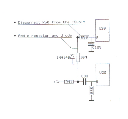
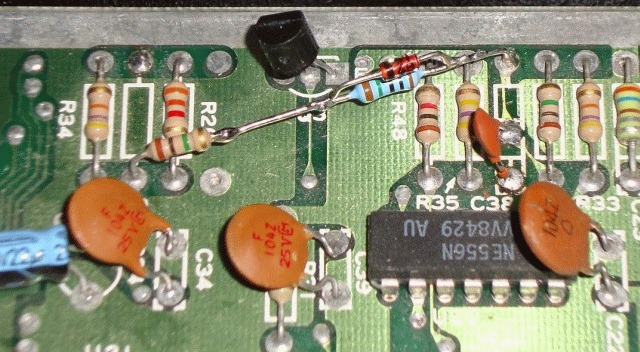
- The TOD (time of day) clock of the C64 is now disabled as it no longer gets the AC signal used for a 50Hz time reference. (however the variables TI$ and TI as used in BASIC will still work). In order for the computer to use it's TOD clock again you must remove R37 and CR1 and R5 and connect (to the point where these components come together, which is at pin 12 of U27) a signal of 50Hz.
Now when you are done doing these modification, check and double check all connection again, switch on the machine and check all voltages during operation.
PLA and audio level
 When working with my C64 I was suddenly surprised by the fact that it
stopped working. The so feared "black" screen ruined my day. I swapped
the C64 for a replacement and kept on working, a few days
later it was time to attempt a repair. So... blablabla Checking the voltages, blabla... clock signal and reset. When I touched
the RAM and other chips I noticed they were not really hotter
then normal. Then I replaced the PLA for another one... but
unfortunately my (tiny) drawer of spare parts contained also a broken PLA
chip (causing a little confusion). When I pulled the PLA from a working
(donor) C64 and put it into the non-functional one, I saw it come back to life,
to confirm the defect I placed the suspected PLA into the working C64
and that stopped working. So it was confirmed I have a broken PLA chip
(well actually 2, as my box of spare components had also a broken PLA
chip). Anyway problem solved.
When working with my C64 I was suddenly surprised by the fact that it
stopped working. The so feared "black" screen ruined my day. I swapped
the C64 for a replacement and kept on working, a few days
later it was time to attempt a repair. So... blablabla Checking the voltages, blabla... clock signal and reset. When I touched
the RAM and other chips I noticed they were not really hotter
then normal. Then I replaced the PLA for another one... but
unfortunately my (tiny) drawer of spare parts contained also a broken PLA
chip (causing a little confusion). When I pulled the PLA from a working
(donor) C64 and put it into the non-functional one, I saw it come back to life,
to confirm the defect I placed the suspected PLA into the working C64
and that stopped working. So it was confirmed I have a broken PLA chip
(well actually 2, as my box of spare components had also a broken PLA
chip). Anyway problem solved.For anyone who doesn't have access to a spare PLA, you can make one yourself using an EPROM (M27C512-90B6 is the preferred type, because timing is critical in the C64, using another type might cause you problems). Visit : http://www.vic20.de/html/eprom_pla_8296_und_c64.html for more information. I ordered a few of these EPROM on ebay and made a replacement PLA, now my machine is up and running and the spare PLA is back in the donor machine.
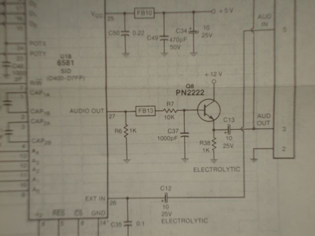
However, I noticed (when I played a little test game) that my audio level was way to low compared to other C64s I own. I never noticed before, but when I did experiments with the donor C64, I noticed the difference. And because the audio sounded so low, I had to boost the monitors volume all the way up, which also increased the (annoying) noise that the audio signal has by default. Time to investigate. In the schematic (see picture below) there is a simple 1 transistor stage fro the audio signal. Which uses an electrolytic capacitor, so perhaps over the years this has dried out... a simple test by bypassing it with a another capacitor makes no difference. The transistor stage is according the "emitter follower" configuration, this simply means that it acts as an impedance matching circuit. In other words, it doesn't boost the signal in voltage but in current. Allowing more current to be drawn by the load, while maintaining the output voltage equal to the input voltage. So, the high impedance of the SID is converted into a low impedance output capable of driving the externally connected audio amplifiers of your monitor or stereo set. But also by lowering the output impedance the signal is less susceptible to noise. Hmmm... what if for some reason the transistor does not meet it's specifications, then it may fail in supplying enough current into my monitors amplifier input, resulting in a too low volume. So I swapped the transistor for a model I knew had no problems, the "good old" BC547. This type has a slightly different pinout, but that is no big problem. And yes, this worked, audio levels are now perfectly OK. The question remains how this problem was created. What could be the cause of this damaged transistor. My theory is that it is damaged by am external power surge. Why do I think so. Well, when I connect my monitor both systems aren't always switched of (my monitor does not have an LED to indicate it's power state) and sometimes I'm just plain stupid, thinking it doesn't matter. But when you use a monitor that has build up a charge for some reason (funny power supply, static electricity, anything) than a current will flow when the connectors meet. When both systems are in the off state, the it is much safer as the current can be absorbed by the capacitance of the switched off power supply circuitry, preventing the effective voltage over the semi conductors reaching a critical level. This isn't without limits, so you always need to take care with static electricity, but the safest way to make a connection is with your equipment in the off state.
Perhaps it would be a good idea to add some extra diodes across the transistor to be more protected against ESD charges.